Honeywell

Honeywell FC-SDIL-1608 V1.3 Safety Manager Safe Loop-Monitored Digital Input Module

SKU FC-SDIL-1608 V1.3

In stock
  • 12-month warranty
  • Free returns within 30 days
  • Manufacturer: Honeywell
  • Product No.: FC-SDIL-1608 V1.3
  • Origin United States
  • Product Type: Digital Input Module
  • Barcode: 8537101190
  • Payment: T/T, Western Union
  • Weight: 0.35 kg
  • Dimensions: 20 x 160 x 100 mm
  • Shipping port: Xiamen
  • Warranty: 12 months

Tags

Product Documentation

Technical Datasheet (PDF) Complete specifications and technical drawings.

Technical Datasheet

Honeywell FC-SDIL-1608 V1.3 Safety Manager Safe Loop-Monitored Digital Input Module

Quantity

Product Description

Description

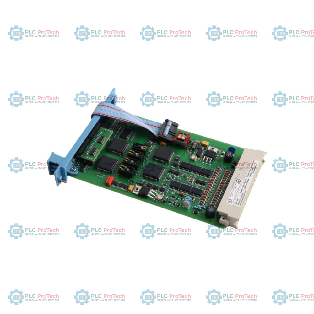
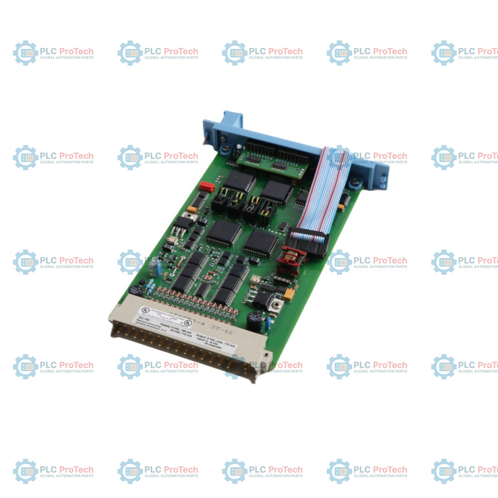
The Honeywell FC-SDIL-1608 V1.3 is a safe, loop-monitored digital input module engineered for critical safety instrumented systems (SIS) within the Honeywell Safety Manager platform. Designed to interface high-integrity digital field signals directly with the controller, this 16-channel module delivers continuous, fail-to-safe monitoring for safety applications, including Emergency Shutdown (ESD), Fire and Gas (F&G) detection, and Burner Management Systems (BMS).

Featuring integrated line and earth fault monitoring, the module continuously tests field wiring for short circuits, open circuits, and ground leaks without interrupting normal system operation. Operating with galvanic isolation between its internal 5 VDC system logic and external field input circuits, the module protects the horizontal IO bus infrastructure from electrical field disturbances while maintaining strict system integrity.

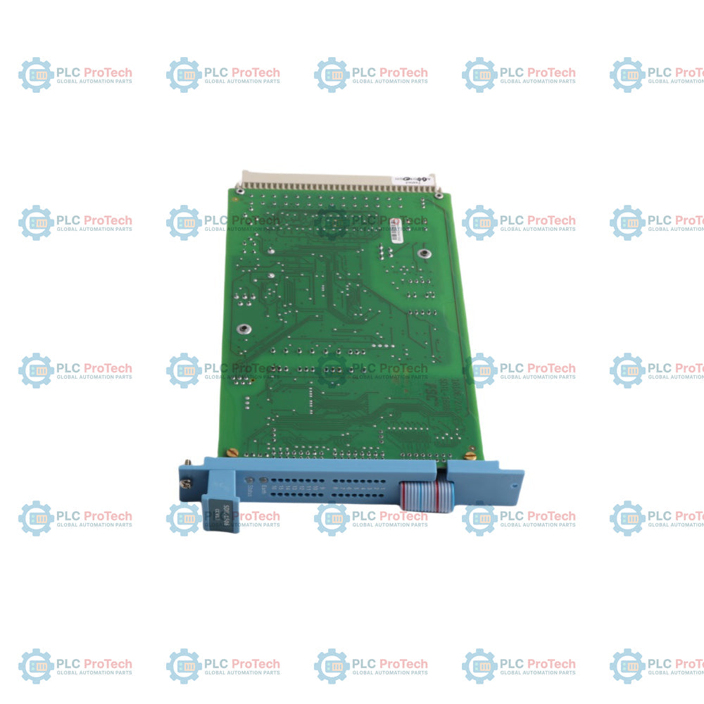
The module executes automated self-test diagnostics within configured intervals, ensuring full diagnostic coverage against component failures, logic state receipt errors, and channel crosstalk. Formatted to the standard European instrument module footprint (4 TE / 4 HP width, 3U height), the FC-SDIL-1608 V1.3 connects to the horizontal IO bus via a front flat cable and uses a DIN 41612 Type F connector for backplane power and signal routing.

Features

  • 16 Safe Digital Input Channels: Supports up to 16 loop-monitored digital inputs for discrete safety switches and field contacts.
  • Integrated Earth Fault Monitoring: Built-in loop supervision continuously monitors for earth faults and line integrity anomalies.
  • Fail-Safe Circuit Design: Configured so that internal component faults default to a de-energized, safe input state.
  • Galvanic Isolation: Complete isolation between internal 5 VDC system bus logic and 24 VDC field input circuits.
  • Continuous Self-Diagnostics: Automated system testing detects component failures, logic state receipt errors, and cross-channel interference within defined test intervals.
  • Hot-Swappable Construction: Standard 4 TE (0.8 in / 3U) European module form factor allows module replacement while system power is applied.
  • Front-Panel Status LEDs: Individual channel status LEDs located on the front panel provide clear, localized visual diagnostic status.

Applications

  • Emergency Shutdown Systems (ESD): Interfaces high-integrity trip pushbuttons, emergency stop switches, and process limit switches.
  • Fire and Gas (F&G) Systems: Monitors loop-powered flame detectors, manual call points, and gas detection contact outputs.
  • Burner Management Systems (BMS): Manages safe digital inputs from fuel gas pressure switches, air proving switches, and valve limit switches.
  • Turbomachinery Protection: Receives trip and interlock contacts from critical rotating equipment monitoring systems.

Technical Specifications

General

Parameter Specification
Manufacturer Honeywell
Model FC-SDIL-1608
Hardware Revision V1.3
Conformal Coating Yes (FC- prefix denotes conformal coated assembly)
Product Type Safe Loop-Monitored Digital Input Module
Target Platform Honeywell Safety Manager
Form Factor Standard European Instrument Module (4 TE / 4 HP width, 3U height)
Module Width 20.32 mm (0.8 in)
Module Connector DIN 41612, Type F (Rows d, b, z in use)

Input & System Ratings

Parameter Specification
Number of Channels 16 channels
Channel Monitoring Loop-monitored with earth fault monitoring
Bus Logic Power 5 VDC
Field Power Nominal Voltage 24 VDC
Field Power Voltage Tolerance 24 VDC (+30% / -15%)
Isolation Galvanic isolation between 5 VDC bus logic and field circuits
Bus Connection Flat cable connection to horizontal IO bus (IOBUS-HBS / IOBUS-HBR)

Connections / Interfaces

Interface / Connection Function
Front Flat Cable Connects the module to the horizontal IO bus (IOBUS-HBS or IOBUS-HBR)
Front Channel LEDs Visual status indication for each of the 16 digital input channels
DIN 41612 Type F Connector Backplane connection handling internal 5 VDC, internal/external 24 VDC supply, and field signal wiring

Installation Guidelines

  1. Pre-Installation Inspection: Verify that the model number matches FC-SDIL-1608 V1.3 and inspect the PCB assembly, DIN edge connector, and front flat cable for physical damage prior to insertion.
  2. Rack Slot Placement: The module address is determined entirely by its slot location in the standard 19-inch IO chassis. No manual jumper or DIP-switch settings are required.
  3. Module Insertion: Carefully align the module card guides in the chassis slot (4 TE width). Gently push the module inward until the backplane DIN 41612 Type F connector is fully seated flush with the chassis.
  4. Mechanical Fastening: Secure the top and bottom retaining screws to ensure proper grounding and mechanical stability against industrial vibration.
  5. Bus Connection: Connect the module front flat cable to the designated horizontal IO bus ribbon connector (IOBUS-HBS or IOBUS-HBR).

Commissioning and Replacement

Commissioning Recommendations

  1. Power Supply Integrity: Verify that the 24 VDC field supply remains within the allowable operating range (+30% / -15%) to prevent fault detection during automatic system self-tests.
  2. Loop Integrity Checks: Verify field wiring loops for open circuits, high-resistance connections, and unwanted ground references before establishing active safety logic loops.
  3. LED Diagnostic Verification: Confirm proper channel LED illumination during field contact actuation to validate end-to-end signal integrity.

Replacement Recommendations

  1. Online Replacement (Hot-Swap): The module can be replaced while chassis power is on. Evaluate process conditions and safety interlocks before removing the module, as removing an active input module may trigger safe-state trip logic depending on IO redundancy.
  2. Removal Sequence: First disconnect the front flat cable from the horizontal IO bus (IOBUS-HBS / IOBUS-HBR). Loosen the top and bottom mounting screws, then gently slide the module straight out of the chassis slot.
  3. Installation Sequence: Slide the replacement module into the assigned slot, seat it flush against the backplane connector, tighten retaining screws, and reconnect the front flat cable to the horizontal IO bus.
Shipping & Returns

Global Express Shipping

  • Standard Delivery: 4–6 business days via DHL, FedEx, and UPS.
  • Express Dispatch: Same-day dispatch for in-stock orders placed before 2:00 PM (GMT+8).
  • Worldwide Coverage: Serving over 150 countries.

Returns & Warranty

  • 30-Day Guarantee: Returns accepted for in-stock products in original, factory-sealed packaging.
  • 12-Month Warranty: Every industrial component is backed by our technical warranty.
FAQ
What is the primary function of the Honeywell FC-SDIL-1608 V1.3 module?
The module is a 16-channel safe loop-monitored digital input module designed for Honeywell Safety Manager systems. It interfaces field switch contacts with the system controller while providing line fault and earth fault monitoring for high-integrity safety applications.
Does the FC-SDIL-1608 V1.3 require address jumpers or software node setup?
No. The module address is automatically determined by its physical slot position within the Safety Manager IO chassis. Modules of the same type are interchangeable without setting jumpers or switches.
Can the FC-SDIL-1608 V1.3 be replaced while the system is powered?
Yes, the module supports replacement with system power applied. However, disconnecting an input module may affect process operation depending on the safety system IO configuration, so loop conditions should be reviewed prior to removal.
What does the 'FC-' prefix indicate on this module?
The 'FC-' prefix designates that the circuit board assembly is conformal coated for added protection against environmental contaminants, whereas 'FS-' prefixes indicate non-conformal coated modules.
Reviews

FC-SDIL-1608 V1.3

Stock & lead time on request

Call
1 of 3

Honeywell FC-SDIL-1608 V1.3 Safety Manager Safe Loop-Monitored Digital Input Module

Only 4 item(s) left in stock
  • Manufacturer: Honeywell

  • Product No.: FC-SDIL-1608 V1.3

  • Country of origin:United States

  • Product Type: Digital Input Module

  • Barcode: 8537101190

  • Payment: T/T, Western Union

  • Weight: 350g

  • Dimensions: 20 x 160 x 100 mm

  • Shipping port: Xiamen

  • Warranty: 12 months

Quantity
View full details

Description

The Honeywell FC-SDIL-1608 V1.3 is a safe, loop-monitored digital input module engineered for critical safety instrumented systems (SIS) within the Honeywell Safety Manager platform. Designed to interface high-integrity digital field signals directly with the controller, this 16-channel module delivers continuous, fail-to-safe monitoring for safety applications, including Emergency Shutdown (ESD), Fire and Gas (F&G) detection, and Burner Management Systems (BMS).

Featuring integrated line and earth fault monitoring, the module continuously tests field wiring for short circuits, open circuits, and ground leaks without interrupting normal system operation. Operating with galvanic isolation between its internal 5 VDC system logic and external field input circuits, the module protects the horizontal IO bus infrastructure from electrical field disturbances while maintaining strict system integrity.

The module executes automated self-test diagnostics within configured intervals, ensuring full diagnostic coverage against component failures, logic state receipt errors, and channel crosstalk. Formatted to the standard European instrument module footprint (4 TE / 4 HP width, 3U height), the FC-SDIL-1608 V1.3 connects to the horizontal IO bus via a front flat cable and uses a DIN 41612 Type F connector for backplane power and signal routing.

Features

  • 16 Safe Digital Input Channels: Supports up to 16 loop-monitored digital inputs for discrete safety switches and field contacts.
  • Integrated Earth Fault Monitoring: Built-in loop supervision continuously monitors for earth faults and line integrity anomalies.
  • Fail-Safe Circuit Design: Configured so that internal component faults default to a de-energized, safe input state.
  • Galvanic Isolation: Complete isolation between internal 5 VDC system bus logic and 24 VDC field input circuits.
  • Continuous Self-Diagnostics: Automated system testing detects component failures, logic state receipt errors, and cross-channel interference within defined test intervals.
  • Hot-Swappable Construction: Standard 4 TE (0.8 in / 3U) European module form factor allows module replacement while system power is applied.
  • Front-Panel Status LEDs: Individual channel status LEDs located on the front panel provide clear, localized visual diagnostic status.

Applications

  • Emergency Shutdown Systems (ESD): Interfaces high-integrity trip pushbuttons, emergency stop switches, and process limit switches.
  • Fire and Gas (F&G) Systems: Monitors loop-powered flame detectors, manual call points, and gas detection contact outputs.
  • Burner Management Systems (BMS): Manages safe digital inputs from fuel gas pressure switches, air proving switches, and valve limit switches.
  • Turbomachinery Protection: Receives trip and interlock contacts from critical rotating equipment monitoring systems.

Technical Specifications

General

Parameter Specification
Manufacturer Honeywell
Model FC-SDIL-1608
Hardware Revision V1.3
Conformal Coating Yes (FC- prefix denotes conformal coated assembly)
Product Type Safe Loop-Monitored Digital Input Module
Target Platform Honeywell Safety Manager
Form Factor Standard European Instrument Module (4 TE / 4 HP width, 3U height)
Module Width 20.32 mm (0.8 in)
Module Connector DIN 41612, Type F (Rows d, b, z in use)

Input & System Ratings

Parameter Specification
Number of Channels 16 channels
Channel Monitoring Loop-monitored with earth fault monitoring
Bus Logic Power 5 VDC
Field Power Nominal Voltage 24 VDC
Field Power Voltage Tolerance 24 VDC (+30% / -15%)
Isolation Galvanic isolation between 5 VDC bus logic and field circuits
Bus Connection Flat cable connection to horizontal IO bus (IOBUS-HBS / IOBUS-HBR)

Connections / Interfaces

Interface / Connection Function
Front Flat Cable Connects the module to the horizontal IO bus (IOBUS-HBS or IOBUS-HBR)
Front Channel LEDs Visual status indication for each of the 16 digital input channels
DIN 41612 Type F Connector Backplane connection handling internal 5 VDC, internal/external 24 VDC supply, and field signal wiring

Installation Guidelines

  1. Pre-Installation Inspection: Verify that the model number matches FC-SDIL-1608 V1.3 and inspect the PCB assembly, DIN edge connector, and front flat cable for physical damage prior to insertion.
  2. Rack Slot Placement: The module address is determined entirely by its slot location in the standard 19-inch IO chassis. No manual jumper or DIP-switch settings are required.
  3. Module Insertion: Carefully align the module card guides in the chassis slot (4 TE width). Gently push the module inward until the backplane DIN 41612 Type F connector is fully seated flush with the chassis.
  4. Mechanical Fastening: Secure the top and bottom retaining screws to ensure proper grounding and mechanical stability against industrial vibration.
  5. Bus Connection: Connect the module front flat cable to the designated horizontal IO bus ribbon connector (IOBUS-HBS or IOBUS-HBR).

Commissioning and Replacement

Commissioning Recommendations

  1. Power Supply Integrity: Verify that the 24 VDC field supply remains within the allowable operating range (+30% / -15%) to prevent fault detection during automatic system self-tests.
  2. Loop Integrity Checks: Verify field wiring loops for open circuits, high-resistance connections, and unwanted ground references before establishing active safety logic loops.
  3. LED Diagnostic Verification: Confirm proper channel LED illumination during field contact actuation to validate end-to-end signal integrity.

Replacement Recommendations

  1. Online Replacement (Hot-Swap): The module can be replaced while chassis power is on. Evaluate process conditions and safety interlocks before removing the module, as removing an active input module may trigger safe-state trip logic depending on IO redundancy.
  2. Removal Sequence: First disconnect the front flat cable from the horizontal IO bus (IOBUS-HBS / IOBUS-HBR). Loosen the top and bottom mounting screws, then gently slide the module straight out of the chassis slot.
  3. Installation Sequence: Slide the replacement module into the assigned slot, seat it flush against the backplane connector, tighten retaining screws, and reconnect the front flat cable to the horizontal IO bus.
Loading product navigation…

Product Documentation

Technical Datasheet (PDF) Complete specifications and technical drawings.

Technical Datasheet

Honeywell FC-SDIL-1608 V1.3 Safety Manager Safe Loop-Monitored Digital Input Module

What is the primary function of the Honeywell FC-SDIL-1608 V1.3 module?

The module is a 16-channel safe loop-monitored digital input module designed for Honeywell Safety Manager systems. It interfaces field switch contacts with the system controller while providing line fault and earth fault monitoring for high-integrity safety applications.

Does the FC-SDIL-1608 V1.3 require address jumpers or software node setup?

No. The module address is automatically determined by its physical slot position within the Safety Manager IO chassis. Modules of the same type are interchangeable without setting jumpers or switches.

Can the FC-SDIL-1608 V1.3 be replaced while the system is powered?

Yes, the module supports replacement with system power applied. However, disconnecting an input module may affect process operation depending on the safety system IO configuration, so loop conditions should be reviewed prior to removal.

What does the 'FC-' prefix indicate on this module?

The 'FC-' prefix designates that the circuit board assembly is conformal coated for added protection against environmental contaminants, whereas 'FS-' prefixes indicate non-conformal coated modules.

Global Express Shipping

  • Standard Delivery: 4-6 Business Days via DHL, FedEx, and UPS.
  • Express Dispatch: Same-day dispatch for in-stock orders placed before 2:00 PM (GMT+8).
  • Worldwide Coverage: Serving over 150 countries, including rapid delivery to Saudi Arabia and UAE.

Returns & Warranty

  • 30-Day Guarantee: Returns accepted for in-stock products in original, factory-sealed packaging.
  • 12-Month Warranty: Every industrial component is backed by our professional technical warranty.

Orders are processed and delivered Monday-Friday (excluding public holidays).


For full eligibility, restocking fees, and international return details, please view our official Refund & Return Policy .

TECHNICAL SPECIFICATIONS

Color pattern
Green
Country of origin
United States
Power source
DC Power

Recently Viewed Products

Technical knowledge

Implementing 3-Switch XOR Ladder Logic with Internal Bit

Implement a 3-SPST switch XOR light circuit in LogixPro or RSLogix 500 using an internal relay bit. Includes truth tables, boolean equations, and verified.

Building a Modbus RTU Network with CompactLogix and DeltaV

Integrate Allen-Bradley CompactLogix, Caterpillar ATS, and generators into DeltaV DCS over Modbus RTU. Covers ProSoft MVI69-MCM, Miille DIN266 gateways.

ONS Instruction Not Energizing OTE in Studio 5000 Ladder Logic

ONS instruction fires but the OTE coil never latches in Studio 5000 because the one-shot is only true for one scan. Use OTL/OTU or seal-in logic instead.

Kinetix 5500 EtherNet/IP Network Switch Requirements and Topology

Configure Allen-Bradley Kinetix 5500 servo drives on EtherNet/IP. Covers CIP Sync, IEEE 1588 V2 timing, Stratix selection, DLR topology, and HMI.

Moving Average Filtering in DCS and PLC Analog Control

A moving-average filter is the sliding-window smoother most instrument engineers drop into DCS and PLC analog paths. Here is how the window works, how N and sample time set lag, and when a...

GE Mark VI Function Blocks for Gas Turbine Control Logic

On Frame 5–9 gas turbines, GE Mark VI and Mark VIe run control as function-block application software. This article maps process, protection, and sequencing functions—and what Toolbox ST access...