Honeywell

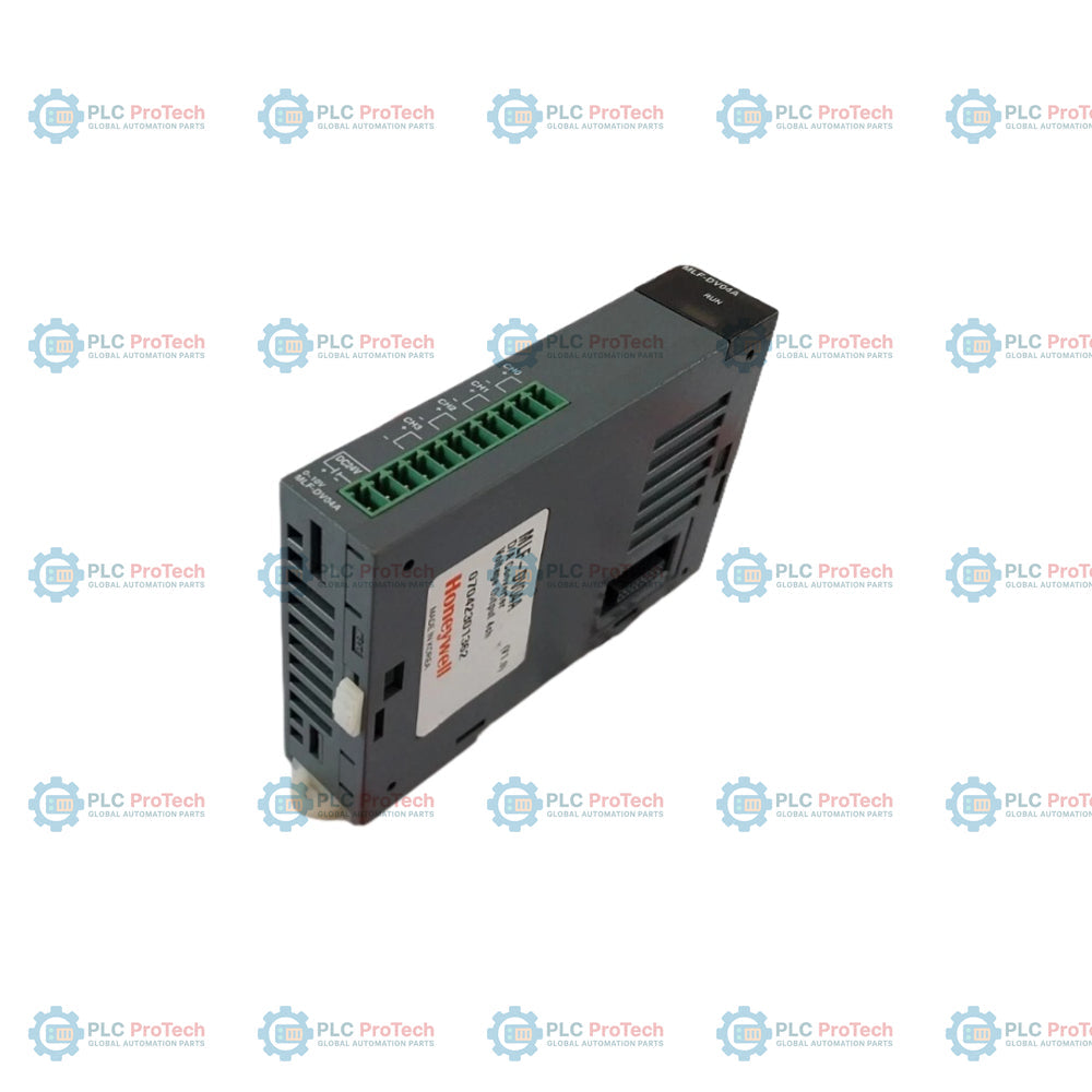
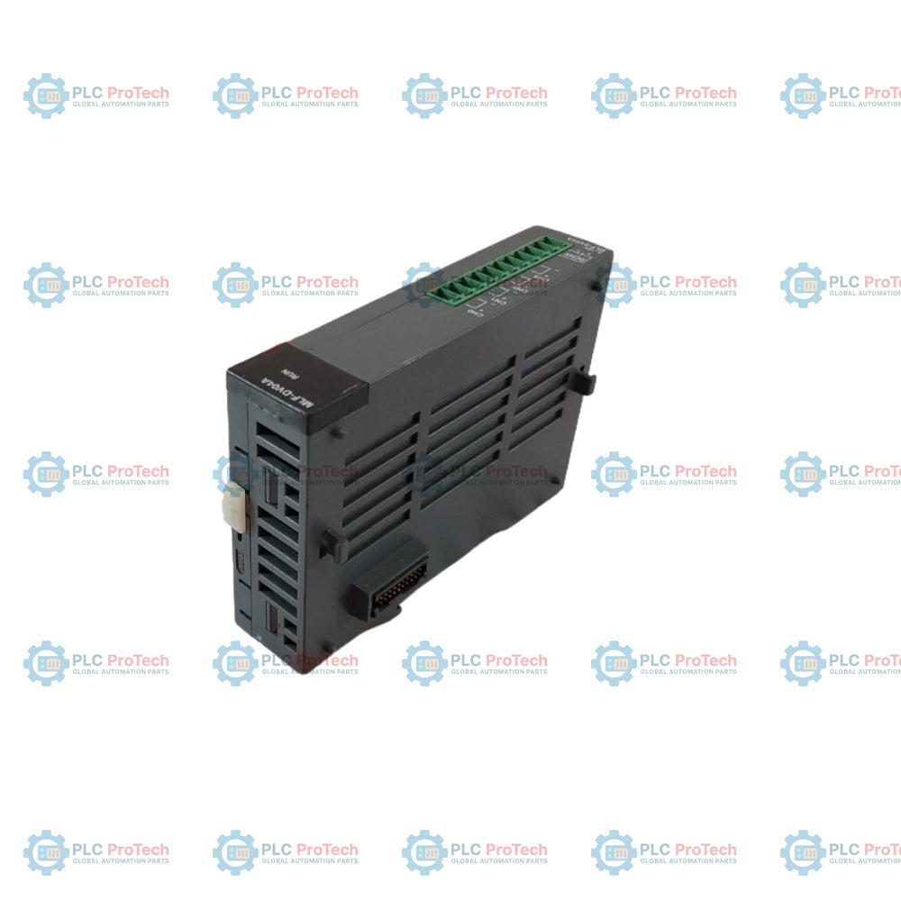
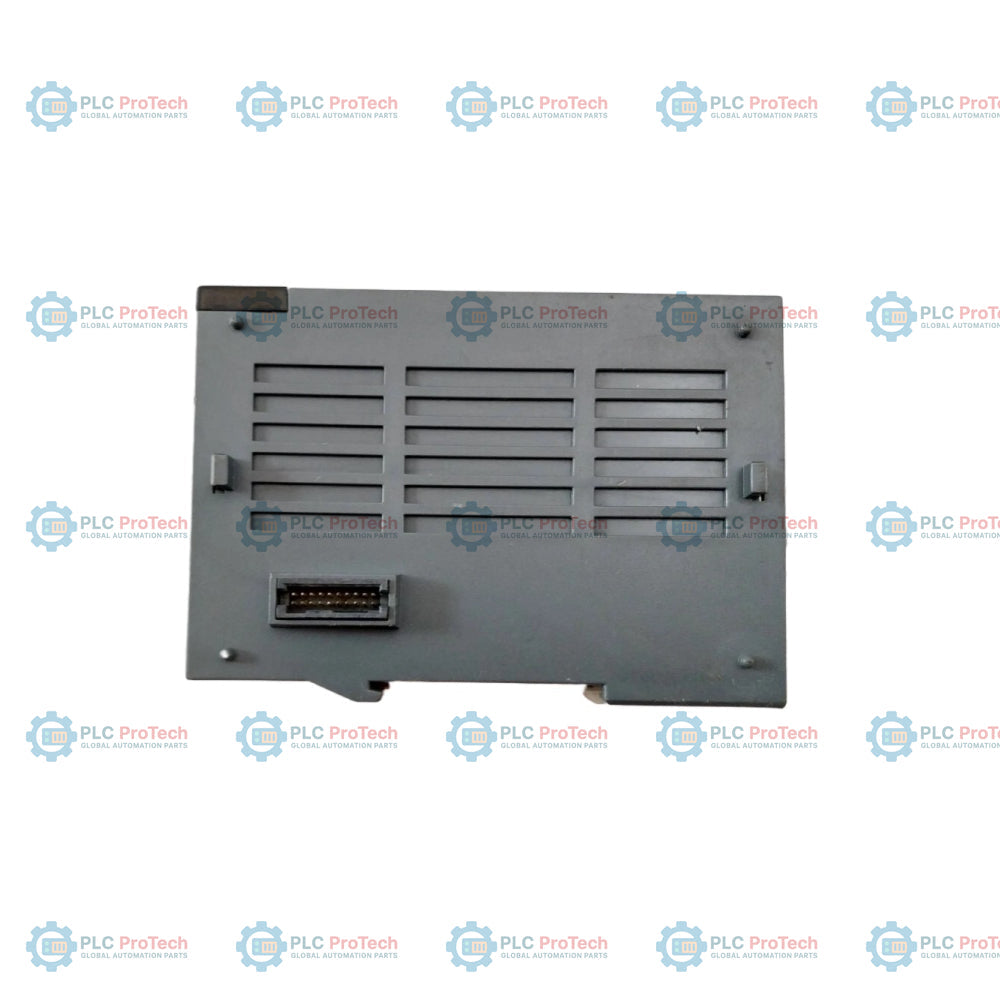
Honeywell MLF-DC04C MasterLogic 50 Analog Output Module

SKU MLF-DC04C

In stock
  • 12-month warranty
  • Free returns within 30 days
  • Manufacturer: Honeywell
  • Product No.: MLF-DC04C
  • Origin United States
  • Product Type: Analog Output Module
  • Barcode: 8537101190
  • Payment: T/T, Western Union
  • Weight: 0.118 kg
  • Dimensions: 27 x 90 x 100 mm
  • Shipping port: Xiamen
  • Warranty: 12 months

Tags

Product Documentation

Technical Datasheet (PDF) Complete specifications and technical drawings.

Technical Datasheet

Honeywell MLF-DC04C MasterLogic 50 Analog Output Module

Quantity

Product Description

Description

The Honeywell MLF-DC04C is a high-resolution 4-channel analog current output module designed for industrial process control and signal generation within the Honeywell MasterLogic 50 (ML50) platform and ControlEdge PLC expansion systems.

The module provides four high-accuracy current output channels operating across standard DC 4 to 20 mA and DC 0 to 20 mA current loops. Featuring a 16-bit binary conversion resolution (14-bit effective data) with a conversion speed of 1.0 ms per channel, the Honeywell MLF-DC04C delivers rapid, steady command signals to downstream field instruments such as control valve positioners, variable frequency drives, actuators, and analog indicators.

Operating with a fixed assignment of 64 I/O points, the module incorporates photo-coupler isolation between the field output terminals and the backplane logic power supply to protect system electronics from electrical transients. External wiring connections are organized using an 11-point removable terminal block, simplifying module mounting and routine field maintenance.

Features

  • Provides 4 high-resolution analog current output channels configurable for DC 4 to 20 mA and DC 0 to 20 mA operating ranges.
  • Delivers 16-bit binary conversion resolution (1/16,000 steps) yielding a current resolution of 1.0 uA for 4 to 20 mA and 1.25 uA for 0 to 20 mA loops.
  • Executes fast digital-to-analog conversion at 1.0 ms per channel.
  • Supports configurable digital data representation modes: Unsigned Value, Signed Value, Precise Value, and Percentile Value.
  • Incorporates photo-coupler isolation between field I/O terminals and the controller power supply.
  • Connects field wiring via an 11-point terminal block interface.
  • Maintains calibrated signal accuracy within +-0.2 percent at ambient temperatures of 25 degC (+-5 degC).
  • Occupies a fixed 64-point I/O allocation in the base rack configuration.

Applications

  • Final Control Element Actuation: Driving analog input positioners for control valves, dampers, and variable speed drives in automated loops.
  • Signal Re-transmission: Converting internal controller variables into standard 4-20 mA or 0-20 mA current signals for chart recorders, digital panel meters, and external monitoring units.
  • DCS and Subsystem Interfacing: Interfacing MasterLogic 50 / ControlEdge PLC controllers with third-party field equipment requiring regulated analog current inputs.

Technical Specifications

Parameter Specification
Model Number MLF-DC04C
Product Type Analog Output Module
Platform / Series MasterLogic 50 (ML50) / ControlEdge PLC
Output Channels 4 channels per module
Analog Output Ranges DC 4 to 20 mA, DC 0 to 20 mA
Digital Data Resolution 16-bit binary value (14-bit effective data; 1/16,000 resolution)
Current Output Resolution 1.0 uA (at 4 to 20 mA), 1.25 uA (at 0 to 20 mA)
Conversion Speed 1.0 ms per channel
Output Accuracy (25 degC +-5 degC) +-0.2% or less
Output Accuracy (0 to 55 degC) +-0.3% or less
Digital Data Modes Unsigned (0-16000), Signed (-8000 to 8000), Precise (4000-20000 / 0-20000), Percentile (0-10000)
Isolation Method Photo-coupler isolation between I/O terminal and PLC power (non-isolated between channels)
Terminal Connection 11-point terminal block
Occupied I/O Points Fixed 64 points
Internal Power Consumption DC 5V @ 75 mA, DC 24V @ 170 mA
Module Weight 118 g

Connections / Interfaces

Interface Function
11-Point Terminal Block Field wiring interface for 4 current output channels and common return paths
Backplane Bus Interface Communication and internal power interface to the MasterLogic 50 base unit

Installation Guidelines

  1. Turn off all system power before mounting or removing the module from the base unit.
  2. Align the module with the base guide slot and press firmly until the locking tab engages securely.
  3. Verify that signal wiring to the 11-point terminal block is properly stripped and secured to prevent short circuits.
  4. Route analog output cables away from high-voltage AC lines to prevent electromagnetic noise coupling.
  5. Connect cable shielding to the ground terminal at a single end of the loop.

Configuration Guidelines

  1. Open ControlEdge Builder or MasterLogic programming software and assign the MLF-DC04C to its designated rack slot.
  2. Select the required current output range (DC 4 to 20 mA or DC 0 to 20 mA) for each channel.
  3. Set the digital data format (Unsigned, Signed, Precise, or Percentile) matching the logic program structure.
  4. Download the hardware configuration to the controller and verify module LED status.

Commissioning Recommendations

  1. Power up the controller system and confirm that the module scan LED blinks green.
  2. Force low, mid, and high values in logic memory and measure physical current outputs at the terminal block using a calibrated meter.
  3. Verify output response at 0 percent, 50 percent, and 100 percent of span (e.g., 4 mA, 12 mA, 20 mA) to confirm loop linearity.

Replacement Recommendations

  1. Place the parent controller in STOP mode or isolate connected field devices before servicing.
  2. Disconnect main power to the rack and unplug the 11-point terminal block from the module.
  3. Release the retention clip and pull the module straight out from the slot.
  4. Slide the replacement MLF-DC04C module into position, reattach the terminal block, restore system power, and verify configuration parameters.
Shipping & Returns

Global Express Shipping

  • Standard Delivery: 4–6 business days via DHL, FedEx, and UPS.
  • Express Dispatch: Same-day dispatch for in-stock orders placed before 2:00 PM (GMT+8).
  • Worldwide Coverage: Serving over 150 countries.

Returns & Warranty

  • 30-Day Guarantee: Returns accepted for in-stock products in original, factory-sealed packaging.
  • 12-Month Warranty: Every industrial component is backed by our technical warranty.
FAQ
What is the primary function of the Honeywell MLF-DC04C analog output module?
The Honeywell MLF-DC04C is a 4-channel analog current output module for MasterLogic 50 controllers, designed to convert 16-bit digital control values into regulated DC 4 to 20 mA or DC 0 to 20 mA current signals to drive actuators, control valves, and signal conditioning equipment.
What signal ranges and conversion resolutions are supported by the Honeywell MLF-DC04C?
The Honeywell MLF-DC04C supports selectable DC 4 to 20 mA and DC 0 to 20 mA output ranges with a 16-bit binary conversion resolution (1/16,000 steps). This yields a fine current resolution of 1.0 uA for 4 to 20 mA loops and 1.25 uA for 0 to 20 mA loops.
What digital data formats can be configured for the Honeywell MLF-DC04C module?
The Honeywell MLF-DC04C allows configuration in four digital data modes: Unsigned Value (0 to 16,000), Signed Value (-8,000 to 8,000), Precise Value (4,000 to 20,000 for 4-20 mA or 0 to 20,000 for 0-20 mA), and Percentile Value (0 to 10,000).
How are electrical noise and field isolation managed on the Honeywell MLF-DC04C?
The Honeywell MLF-DC04C utilizes photo-coupler isolation to separate the field I/O terminals from the internal PLC logic power supply, protecting system electronics from external surges and electrical noise, though individual channels share a common ground reference.
Reviews

MLF-DC04C

Stock & lead time on request

Call
1 of 3

Honeywell MLF-DC04C MasterLogic 50 Analog Output Module

Only 8 item(s) left in stock
  • Manufacturer: Honeywell

  • Product No.: MLF-DC04C

  • Country of origin:United States

  • Product Type: Analog Output Module

  • Barcode: 8537101190

  • Payment: T/T, Western Union

  • Weight: 118g

  • Dimensions: 27 x 90 x 100 mm

  • Shipping port: Xiamen

  • Warranty: 12 months

Quantity
View full details

Description

The Honeywell MLF-DC04C is a high-resolution 4-channel analog current output module designed for industrial process control and signal generation within the Honeywell MasterLogic 50 (ML50) platform and ControlEdge PLC expansion systems.

The module provides four high-accuracy current output channels operating across standard DC 4 to 20 mA and DC 0 to 20 mA current loops. Featuring a 16-bit binary conversion resolution (14-bit effective data) with a conversion speed of 1.0 ms per channel, the Honeywell MLF-DC04C delivers rapid, steady command signals to downstream field instruments such as control valve positioners, variable frequency drives, actuators, and analog indicators.

Operating with a fixed assignment of 64 I/O points, the module incorporates photo-coupler isolation between the field output terminals and the backplane logic power supply to protect system electronics from electrical transients. External wiring connections are organized using an 11-point removable terminal block, simplifying module mounting and routine field maintenance.

Features

  • Provides 4 high-resolution analog current output channels configurable for DC 4 to 20 mA and DC 0 to 20 mA operating ranges.
  • Delivers 16-bit binary conversion resolution (1/16,000 steps) yielding a current resolution of 1.0 uA for 4 to 20 mA and 1.25 uA for 0 to 20 mA loops.
  • Executes fast digital-to-analog conversion at 1.0 ms per channel.
  • Supports configurable digital data representation modes: Unsigned Value, Signed Value, Precise Value, and Percentile Value.
  • Incorporates photo-coupler isolation between field I/O terminals and the controller power supply.
  • Connects field wiring via an 11-point terminal block interface.
  • Maintains calibrated signal accuracy within +-0.2 percent at ambient temperatures of 25 degC (+-5 degC).
  • Occupies a fixed 64-point I/O allocation in the base rack configuration.

Applications

  • Final Control Element Actuation: Driving analog input positioners for control valves, dampers, and variable speed drives in automated loops.
  • Signal Re-transmission: Converting internal controller variables into standard 4-20 mA or 0-20 mA current signals for chart recorders, digital panel meters, and external monitoring units.
  • DCS and Subsystem Interfacing: Interfacing MasterLogic 50 / ControlEdge PLC controllers with third-party field equipment requiring regulated analog current inputs.

Technical Specifications

Parameter Specification
Model Number MLF-DC04C
Product Type Analog Output Module
Platform / Series MasterLogic 50 (ML50) / ControlEdge PLC
Output Channels 4 channels per module
Analog Output Ranges DC 4 to 20 mA, DC 0 to 20 mA
Digital Data Resolution 16-bit binary value (14-bit effective data; 1/16,000 resolution)
Current Output Resolution 1.0 uA (at 4 to 20 mA), 1.25 uA (at 0 to 20 mA)
Conversion Speed 1.0 ms per channel
Output Accuracy (25 degC +-5 degC) +-0.2% or less
Output Accuracy (0 to 55 degC) +-0.3% or less
Digital Data Modes Unsigned (0-16000), Signed (-8000 to 8000), Precise (4000-20000 / 0-20000), Percentile (0-10000)
Isolation Method Photo-coupler isolation between I/O terminal and PLC power (non-isolated between channels)
Terminal Connection 11-point terminal block
Occupied I/O Points Fixed 64 points
Internal Power Consumption DC 5V @ 75 mA, DC 24V @ 170 mA
Module Weight 118 g

Connections / Interfaces

Interface Function
11-Point Terminal Block Field wiring interface for 4 current output channels and common return paths
Backplane Bus Interface Communication and internal power interface to the MasterLogic 50 base unit

Installation Guidelines

  1. Turn off all system power before mounting or removing the module from the base unit.
  2. Align the module with the base guide slot and press firmly until the locking tab engages securely.
  3. Verify that signal wiring to the 11-point terminal block is properly stripped and secured to prevent short circuits.
  4. Route analog output cables away from high-voltage AC lines to prevent electromagnetic noise coupling.
  5. Connect cable shielding to the ground terminal at a single end of the loop.

Configuration Guidelines

  1. Open ControlEdge Builder or MasterLogic programming software and assign the MLF-DC04C to its designated rack slot.
  2. Select the required current output range (DC 4 to 20 mA or DC 0 to 20 mA) for each channel.
  3. Set the digital data format (Unsigned, Signed, Precise, or Percentile) matching the logic program structure.
  4. Download the hardware configuration to the controller and verify module LED status.

Commissioning Recommendations

  1. Power up the controller system and confirm that the module scan LED blinks green.
  2. Force low, mid, and high values in logic memory and measure physical current outputs at the terminal block using a calibrated meter.
  3. Verify output response at 0 percent, 50 percent, and 100 percent of span (e.g., 4 mA, 12 mA, 20 mA) to confirm loop linearity.

Replacement Recommendations

  1. Place the parent controller in STOP mode or isolate connected field devices before servicing.
  2. Disconnect main power to the rack and unplug the 11-point terminal block from the module.
  3. Release the retention clip and pull the module straight out from the slot.
  4. Slide the replacement MLF-DC04C module into position, reattach the terminal block, restore system power, and verify configuration parameters.
Loading product navigation…

Product Documentation

Technical Datasheet (PDF) Complete specifications and technical drawings.

Technical Datasheet

Honeywell MLF-DC04C MasterLogic 50 Analog Output Module

What is the primary function of the Honeywell MLF-DC04C analog output module?

The Honeywell MLF-DC04C is a 4-channel analog current output module for MasterLogic 50 controllers, designed to convert 16-bit digital control values into regulated DC 4 to 20 mA or DC 0 to 20 mA current signals to drive actuators, control valves, and signal conditioning equipment.

What signal ranges and conversion resolutions are supported by the Honeywell MLF-DC04C?

The Honeywell MLF-DC04C supports selectable DC 4 to 20 mA and DC 0 to 20 mA output ranges with a 16-bit binary conversion resolution (1/16,000 steps). This yields a fine current resolution of 1.0 uA for 4 to 20 mA loops and 1.25 uA for 0 to 20 mA loops.

What digital data formats can be configured for the Honeywell MLF-DC04C module?

The Honeywell MLF-DC04C allows configuration in four digital data modes: Unsigned Value (0 to 16,000), Signed Value (-8,000 to 8,000), Precise Value (4,000 to 20,000 for 4-20 mA or 0 to 20,000 for 0-20 mA), and Percentile Value (0 to 10,000).

How are electrical noise and field isolation managed on the Honeywell MLF-DC04C?

The Honeywell MLF-DC04C utilizes photo-coupler isolation to separate the field I/O terminals from the internal PLC logic power supply, protecting system electronics from external surges and electrical noise, though individual channels share a common ground reference.

Global Express Shipping

  • Standard Delivery: 4-6 Business Days via DHL, FedEx, and UPS.
  • Express Dispatch: Same-day dispatch for in-stock orders placed before 2:00 PM (GMT+8).
  • Worldwide Coverage: Serving over 150 countries, including rapid delivery to Saudi Arabia and UAE.

Returns & Warranty

  • 30-Day Guarantee: Returns accepted for in-stock products in original, factory-sealed packaging.
  • 12-Month Warranty: Every industrial component is backed by our professional technical warranty.

Orders are processed and delivered Monday-Friday (excluding public holidays).


For full eligibility, restocking fees, and international return details, please view our official Refund & Return Policy .

TECHNICAL SPECIFICATIONS

Color pattern
Black
Country of origin
United States
Power source
DC Power

Recently Viewed Products

Technical knowledge

Implementing 3-Switch XOR Ladder Logic with Internal Bit

Implement a 3-SPST switch XOR light circuit in LogixPro or RSLogix 500 using an internal relay bit. Includes truth tables, boolean equations, and verified.

Building a Modbus RTU Network with CompactLogix and DeltaV

Integrate Allen-Bradley CompactLogix, Caterpillar ATS, and generators into DeltaV DCS over Modbus RTU. Covers ProSoft MVI69-MCM, Miille DIN266 gateways.

ONS Instruction Not Energizing OTE in Studio 5000 Ladder Logic

ONS instruction fires but the OTE coil never latches in Studio 5000 because the one-shot is only true for one scan. Use OTL/OTU or seal-in logic instead.

Kinetix 5500 EtherNet/IP Network Switch Requirements and Topology

Configure Allen-Bradley Kinetix 5500 servo drives on EtherNet/IP. Covers CIP Sync, IEEE 1588 V2 timing, Stratix selection, DLR topology, and HMI.

Moving Average Filtering in DCS and PLC Analog Control

A moving-average filter is the sliding-window smoother most instrument engineers drop into DCS and PLC analog paths. Here is how the window works, how N and sample time set lag, and when a...

GE Mark VI Function Blocks for Gas Turbine Control Logic

On Frame 5–9 gas turbines, GE Mark VI and Mark VIe run control as function-block application software. This article maps process, protection, and sequencing functions—and what Toolbox ST access...