Product Overview
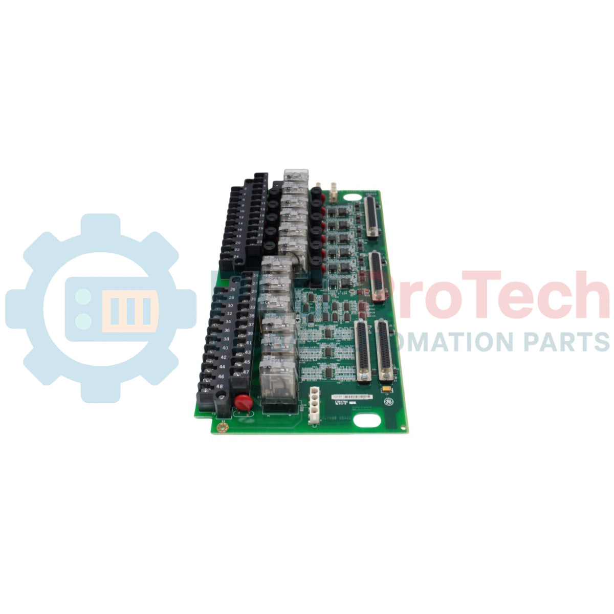
The IS200TRLYH1B serves as a high-density Relay Output Terminal Board (TRLY) within the GE Mark VI Speedtronic control system. This board provides the essential interface for auxiliary control functions that require dry contact outputs to drive external equipment. Unlike the emergency-focused TREG board, the IS200TRLYH1B manages general-purpose logic, such as starting motor pumps, actuating enclosure fans, and signaling remote DCS systems. It supports both Simplex and Triple Modular Redundant (TMR) configurations, receiving drive signals from the I/O processors and converting them into robust physical switch states. With its integrated terminal blocks and standardized ribbon cable headers, the TRLY board simplifies cabinet wiring while maintaining the high electrical isolation necessary for power plant reliability.
Core Technical Advantages
High-Density Auxiliary Control
The IS200TRLYH1B consolidates 12 to 24 independent relay channels (depending on configuration) onto a single PCB. This high-density layout reduces the footprint required in the control cabinet, allowing for complex automation sequences—such as lube oil system management or cooling water sequencing—to be managed from a centralized hardware node.
Flexible TMR Voting Architecture
When utilized in a TMR system, the board accepts control inputs from the <R>, <S>, and <T> cores. The hardware executes a 2-out-of-3 voting process for each output, ensuring that a failure in a single control cable or processor does not result in an unintended state change of the auxiliary equipment.
Onboard Diagnostic Monitoring
The TRLY board provides real-time "Contact Feedback" to the Mark VI system. It monitors the continuity of the relay coils and the state of the output contacts. If a relay fails to transition after a command is issued, the board immediately generates a "Logic Mismatch" alarm, allowing operators to identify the specific faulty channel without manual circuit tracing.
Technical Specifications
| Parameter |
Specification |
| Control Platform |
Mark VI Speedtronic |
| Board Function |
Auxiliary Relay Output (TRLY) |
| Relay Type |
Sealed Electromechanical Relays |
| Contact Configuration |
Form-C (SPDT) or Form-A (SPST) |
| Max Contact Rating |
125V DC @ 2A / 250V AC @ 5A |
| Response Time |
< 10ms (Typical) |
| Isolation Strength |
1.5kV between Coil and Contacts |
| Revision Level |
H1B (Enhanced Reliability Revision) |
Installation and Maintenance Guide
Terminal Block Wiring and Ferrules
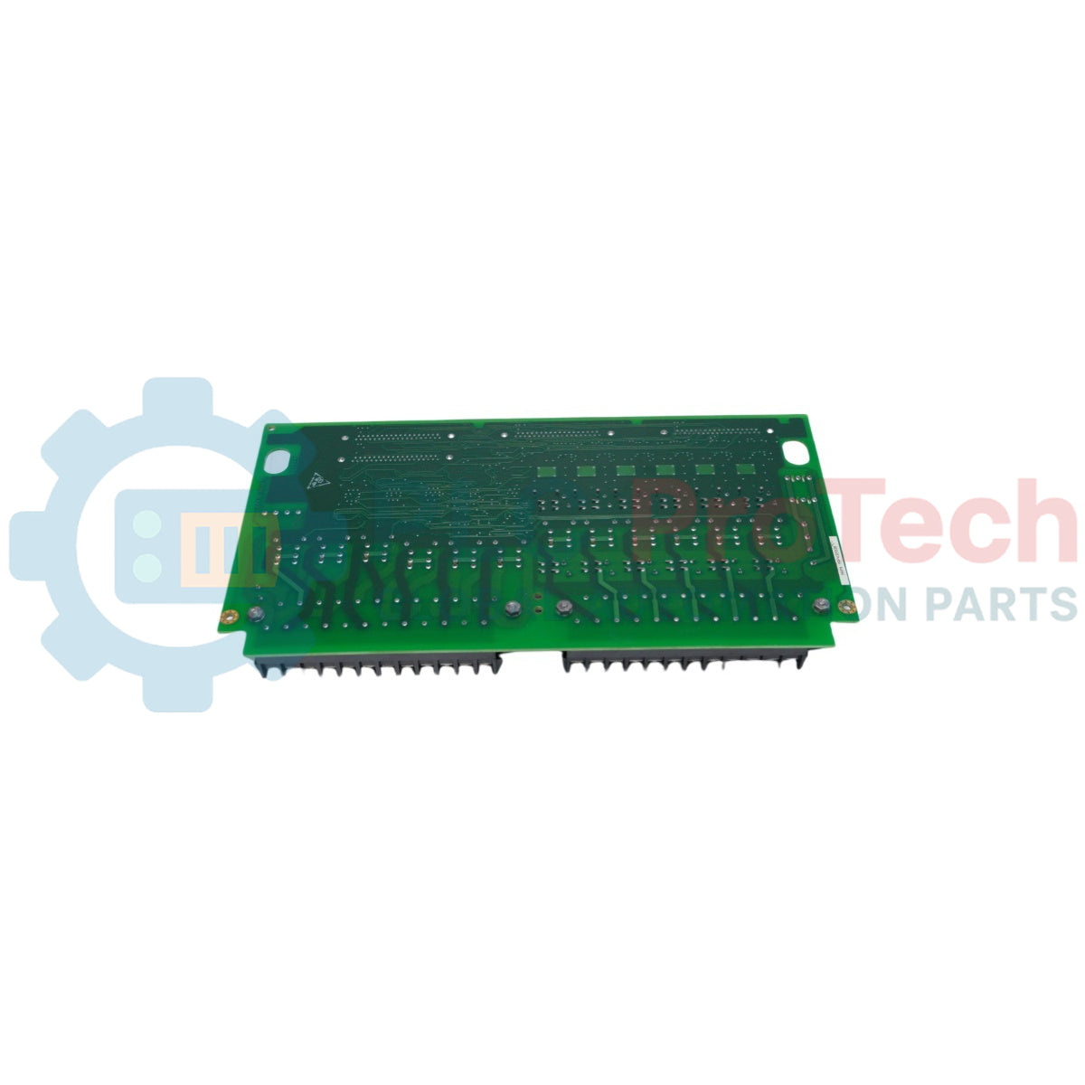
The IS200TRLYH1B features two rows of heavy-duty screw terminals. Use 1.5mm² (16 AWG) wire for control circuits and always apply insulated ferrules to prevent "stray hair" shorts. Tighten all terminals to 0.56 Nm (5 in-lb). Ensure that AC and DC wiring are routed through separate wire ducts to minimize inductive noise coupling.
Fuse Protection and Replacement
Most TRLY variants include individual fuses or fuseless limiters for the output channels. If a specific relay fails to actuate the field device, check the continuity of the associated fuse. Always replace fuses with the exact GE-specified amperage to prevent damage to the board's internal copper traces during a field short circuit.
Ribbon Cable Routing
Connect the TRLY board to the VCMI or VRTD processor boards using the 50-pin ribbon cables. Ensure the cables are routed away from high-current AC busbars. Use the built-in locking tabs on the board’s headers to prevent cables from vibrating loose over time, which is a common cause of intermittent "I/O Communication Failure" alarms.
Engineering Advantages
The IS200TRLYH1B is designed to withstand the harsh thermal and electrical conditions of a turbine enclosure. The H1B revision utilizes gold-flashed relay contacts to prevent oxidation in low-signal (dry contact) applications, ensuring long-term switching reliability. Because the board is a native Mark VI component, it integrates perfectly with the ToolboxST configuration software, enabling "drag-and-drop" logic assignment and real-time forced-bit testing for commissioning and troubleshooting.
Technical FAQs
Q1: Can the IS200TRLYH1B be used for E-Stop functions?
A1: While the TRLY board is highly reliable, it is intended for auxiliary control. Critical emergency trip functions should be routed through the TREG board, which features the specialized 2-out-of-3 hardware voting required for turbine safety strings.
Q2: What is the benefit of the H1B revision over earlier versions?
A2: The H1B revision typically includes improved relay vibration resistance and an optimized PCB layout for better heat dissipation. It is a direct "form-fit-function" replacement for older TRLY boards but offers superior MTBF in high-vibration environments.
Q3: How do I test a specific relay channel without running the turbine?
A3: Using the Mark VI Maintenance Station, you can "Force" the digital output bit associated with the relay. Observe the onboard LED (if available) and use a multimeter to check for continuity across the terminal points. Ensure all field interlocks are cleared before forcing outputs.
Q4: Does this board support both 110V AC and 125V DC loads simultaneously?
A4: Yes, provided the loads are connected to different relay channels. Each relay is galvanically isolated from the others, allowing you to mix AC and DC voltages on the same board, though you must maintain proper separation in your external wiring ducts for safety.