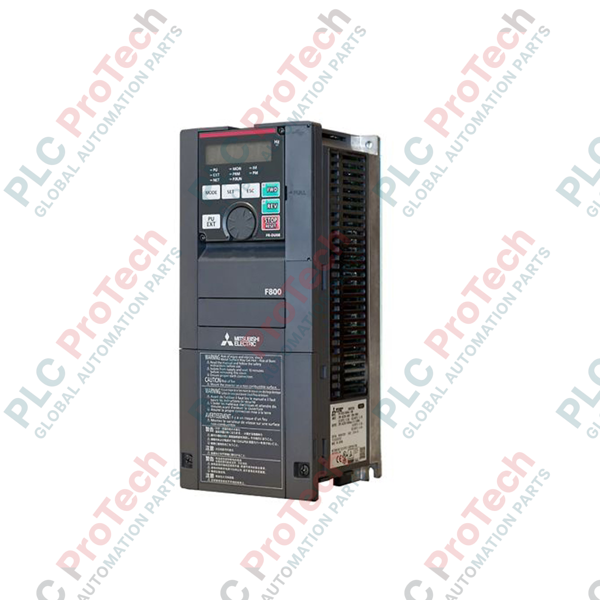
Description
Engineered for high-capacity industrial pump, fan, and HVAC applications, the FR-F840-03610-2-60 is a high-efficiency variable frequency drive (VFD) from the Mitsubishi Electric FR-F800 series. This three-phase inverter optimizes energy consumption through advanced motor excitation algorithms and sophisticated PID control functions. Designed to drive induction and permanent magnet motors, it provides precise speed control and torque management under varied load profiles.
The unit features integrated safety and network integration mechanisms, facilitating seamless deployment into decentralized DCS or PLC architectures. With its built-in EMC filter and robust electrical protections, it handles demanding heavy industrial environments while minimizing electromagnetic interference on adjacent control wiring.
Features
- Advanced Optimum Excitation Control constantly adjusts excitation current to achieve maximum motor efficiency under changing load conditions.
- Dual rating specification (Super Light Duty and Light Duty) allows optimal sizing based on system application demands.
- Integrated PID controller supports multi-pump control, sleep mode, and water hammer prevention functions.
- Built-in Safety Torque Off (STO) function compliant with international safety standards for secure emergency stops.
- Built-in EMC filter limits electromagnetic noise emissions to maintain control signal integrity.
- Support for multiple industrial communication protocols via optional option cards, including CC-Link, Profibus-DP, and EtherCAT.
Applications
- Municipal water supply and wastewater treatment pumping stations.
- Large-scale industrial ventilation fans and air handling units (AHUs).
- Cooling towers and secondary cooling water circulation loops.
- Boiler feed pumps and exhaust gas extraction systems.
- Chiller control and commercial building automation systems.
Technical Specifications
| Manufacturer |
Mitsubishi Electric |
| Model Number |
FR-F840-03610-2-60 |
| Series |
FR-F800 |
| Input Voltage Class |
400V Class (Three-Phase 380 to 500 V AC) |
| Input Frequency Range |
50 / 60 Hz (plus/minus 5%) |
| Rated Current (SLD - Super Light Duty) |
361 A |
| Rated Current (LD - Light Duty) |
310 A |
| Applicable Motor Capacity (SLD) |
185 kW |
| Applicable Motor Capacity (LD) |
160 kW |
| Control Method |
V/F Control, Advanced Magnetic Flux Vector Control, Real Sensorless Vector Control, Optimum Excitation Control |
| Enclosure Protection Rating |
IP00 (Open Type) |
| Cooling Method |
Forced Air Cooling |
| Operating Temperature |
-10 to 50 degC (non-freezing) |
| Approximate Weight |
80 kg |
Connections and Interfaces
| Terminal Group |
Function Description |
| R/L1, S/L2, T/L3 |
Three-phase AC power input connections |
| U, V, W |
Three-phase AC output connections to motor |
| P/+, N/- |
DC bus link terminals for regenerative brake options or shared DC bus configurations |
| Control Terminals |
Multi-function digital inputs, analog current/voltage inputs, open-collector and relay output terminals |
| Ethernet/PU Port |
RJ-45 connector for parameter unit connection and Modbus RTU communication |
Installation Guidelines
-
Mounting Position: Install the inverter vertically on a flat, non-combustible surface. Maintain minimum clearances above, below, and to the sides of the chassis to ensure unobstructed airflow from the cooling fans.
-
Thermal Management: In enclosed control cabinets, ensure the heat dissipation capacity is sufficient to handle the thermal load of an 80 kg drive operating at full load. Use auxiliary extraction fans if cabinet ambient exceeds 40 degC.
-
Shielding and Grounding: Always ground the inverter protective earth (PE) terminal. Use shielded motor cables with proper 360-degree EMC clamp connections to minimize high-frequency noise leakage.
-
Main Circuit Wiring: Select wire gauges capable of carrying the full rated input/output currents of 361A/310A. Ensure high-torque termination on main power lugs to prevent hot spots.