


Implementing 3-Switch XOR Ladder Logic with Internal Bit
Implement a 3-SPST switch XOR light circuit in LogixPro or RSLogix 500 using an internal relay bit. Includes truth tables, boolean equations, and verified.

Designed for high-performance motion architectures within the Sysmac platform, the Omron NX-PG0232-5 acts as a dedicated dual-channel pulse output module that enables precise open-loop control of servo and stepper drives. This module supports synchronous I/O refreshing, allowing high-speed, deterministic synchronization with the main controller over EtherCAT. Featuring a high-density 34-pin MIL connector and robust line driver outputs, it ensures reliable pulse transmission even in electrically noisy industrial environments.
| Parameter | Specification |
|---|---|
| Manufacturer | Omron |
| Model Reference | NX-PG0232-5 |
| Number of Channels | 2 channels |
| Pulse Output Form | Line driver output (NPN type) |
| Maximum Pulse Rate | 4,000,000 pps (4 Mpps) |
| I/O Refreshing Methods | Synchronous I/O refreshing, Task period prioritized refreshing |
| Inputs per Channel | 5 (External inputs) |
| Outputs per Channel | 5 (1 forward pulse, 1 reverse pulse, 3 general-purpose outputs) |
| Position Control Range | -2,147,483,648 to 2,147,483,647 pulses |
| Velocity Control Range | 1 to 4,000,000 pps |
| External Interface | MIL connector (34-pin x 1) |
| Current Consumption (I/O) | 50 mA maximum |
| Maximum Cable Length | Line driver: 10 m | General I/O: 3 m |
| Dimensions (W x H x D) | 30 x 100 x 71 mm |
| Net Weight | 0.11 kg |
| Shipping Weight (Calculated) | 1.00 kg |
When selecting pulse train modules, ensure compatibility with the driver interface: the NX-PG0232-5 uses line driver outputs, which offer superior noise immunity over open-collector variants (such as the NX-PG0112 / NX-PG0122 series). If your servo driver requires a PNP common configuration or single-ended open collector outputs, you must select the corresponding NX-PG variant to avoid hardware mismatch. Sysmac Studio version 1.10 or higher is recommended to configure synchronous motion control options with this unit.
To avoid high-frequency pulse signal attenuation and signal distortion, line driver cables must not exceed 10 meters in length. Exceeding this limit can cause position drift or "lost pulses" during high-velocity moves (above 2 Mpps). Additionally, when units are installed in tightly sealed panels, ensure that adjacent heat-generating components do not drive ambient temperatures above 55 degC, as thermal saturation can degrade internal optocoupler switching performance.
Always use twisted-pair shielded cabling for the line driver pulse outputs. Connect the shield securely to the functional ground bar on the DIN rail. It is highly recommended to use pre-assembled Omron MIL-connector cables (e.g., XW2Z series) to eliminate wiring errors on the high-density 34-pin interface. Keep the pulse signal lines separated from AC power supply cables and variable-frequency drive (VFD) motor lines by at least 100 mm to prevent electromagnetic cross-talk.
Disconnect all power supplies to the NX-series bus coupler and the external I/O power supply before inserting or removing the module. Failure to do so may result in permanent damage to the internal bus transceiver or cause erratic behavior in adjacent modules.
Global Express Shipping
Returns & Warranty

Manufacturer: Omron
Product No.: NX-PG0232-5
Country of origin:Japan
Product Type: Pulse Output Modules
Payment: T/T, Western Union
Weight: 110g
Dimensions: 30 x 100 x 71 mm
Shipping port: Xiamen
Warranty: 12 months
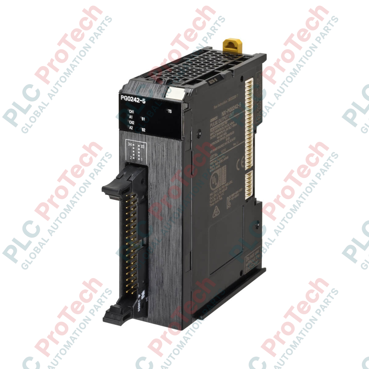
Designed for high-performance motion architectures within the Sysmac platform, the Omron NX-PG0232-5 acts as a dedicated dual-channel pulse output module that enables precise open-loop control of servo and stepper drives. This module supports synchronous I/O refreshing, allowing high-speed, deterministic synchronization with the main controller over EtherCAT. Featuring a high-density 34-pin MIL connector and robust line driver outputs, it ensures reliable pulse transmission even in electrically noisy industrial environments.
| Parameter | Specification |
|---|---|
| Manufacturer | Omron |
| Model Reference | NX-PG0232-5 |
| Number of Channels | 2 channels |
| Pulse Output Form | Line driver output (NPN type) |
| Maximum Pulse Rate | 4,000,000 pps (4 Mpps) |
| I/O Refreshing Methods | Synchronous I/O refreshing, Task period prioritized refreshing |
| Inputs per Channel | 5 (External inputs) |
| Outputs per Channel | 5 (1 forward pulse, 1 reverse pulse, 3 general-purpose outputs) |
| Position Control Range | -2,147,483,648 to 2,147,483,647 pulses |
| Velocity Control Range | 1 to 4,000,000 pps |
| External Interface | MIL connector (34-pin x 1) |
| Current Consumption (I/O) | 50 mA maximum |
| Maximum Cable Length | Line driver: 10 m | General I/O: 3 m |
| Dimensions (W x H x D) | 30 x 100 x 71 mm |
| Net Weight | 0.11 kg |
| Shipping Weight (Calculated) | 1.00 kg |
When selecting pulse train modules, ensure compatibility with the driver interface: the NX-PG0232-5 uses line driver outputs, which offer superior noise immunity over open-collector variants (such as the NX-PG0112 / NX-PG0122 series). If your servo driver requires a PNP common configuration or single-ended open collector outputs, you must select the corresponding NX-PG variant to avoid hardware mismatch. Sysmac Studio version 1.10 or higher is recommended to configure synchronous motion control options with this unit.
To avoid high-frequency pulse signal attenuation and signal distortion, line driver cables must not exceed 10 meters in length. Exceeding this limit can cause position drift or "lost pulses" during high-velocity moves (above 2 Mpps). Additionally, when units are installed in tightly sealed panels, ensure that adjacent heat-generating components do not drive ambient temperatures above 55 degC, as thermal saturation can degrade internal optocoupler switching performance.
Always use twisted-pair shielded cabling for the line driver pulse outputs. Connect the shield securely to the functional ground bar on the DIN rail. It is highly recommended to use pre-assembled Omron MIL-connector cables (e.g., XW2Z series) to eliminate wiring errors on the high-density 34-pin interface. Keep the pulse signal lines separated from AC power supply cables and variable-frequency drive (VFD) motor lines by at least 100 mm to prevent electromagnetic cross-talk.
Disconnect all power supplies to the NX-series bus coupler and the external I/O power supply before inserting or removing the module. Failure to do so may result in permanent damage to the internal bus transceiver or cause erratic behavior in adjacent modules.
Global Express Shipping
Returns & Warranty
Orders are processed and delivered Monday-Friday (excluding public holidays).
For full eligibility, restocking fees, and international return details, please view our official Refund & Return Policy .
| Country of origin |
Japan
|

Implement a 3-SPST switch XOR light circuit in LogixPro or RSLogix 500 using an internal relay bit. Includes truth tables, boolean equations, and verified.

Integrate Allen-Bradley CompactLogix, Caterpillar ATS, and generators into DeltaV DCS over Modbus RTU. Covers ProSoft MVI69-MCM, Miille DIN266 gateways.

ONS instruction fires but the OTE coil never latches in Studio 5000 because the one-shot is only true for one scan. Use OTL/OTU or seal-in logic instead.

Configure Allen-Bradley Kinetix 5500 servo drives on EtherNet/IP. Covers CIP Sync, IEEE 1588 V2 timing, Stratix selection, DLR topology, and HMI.

A moving-average filter is the sliding-window smoother most instrument engineers drop into DCS and PLC analog paths. Here is how the window works, how N and sample time set lag, and when a...

On Frame 5–9 gas turbines, GE Mark VI and Mark VIe run control as function-block application software. This article maps process, protection, and sequencing functions—and what Toolbox ST access...