


Implementing 3-Switch XOR Ladder Logic with Internal Bit
Implement a 3-SPST switch XOR light circuit in LogixPro or RSLogix 500 using an internal relay bit. Includes truth tables, boolean equations, and verified.

Operating as a high-efficiency electrical conversion module, the Omron S8VK-WA24024 delivers stable direct current to demanding industrial automation networks from a three-phase power source. This switch-mode power supply is engineered to mitigate phase unbalance risks and provide continuous, reliable 24 VDC output within compact control cabinets. Designed with a robust covered housing and integrating Omron's proprietary Push-In Plus terminal connection technology, the unit minimizes installation labor while maximizing resistance to physical vibrations common in heavy industrial manufacturing environments.
| Specification Parameter | Verified Engineering Value |
|---|---|
| Manufacturer | Omron |
| Model Number | S8VK-WA24024 |
| Series Name | S8VK-W |
| Rated Input Voltage | 200 to 240 VAC (Three-Phase) |
| Power Rating | 240 W |
| Rated Output Voltage | 24 VDC |
| Rated Output Current | 10 A |
| Maximum Boost Current | 15 A |
| Terminal Type | Push-In Plus Terminal Block |
| Construction Type | Covered |
| Degree of Protection | IP20 (EN/IEC 60529) |
| Unit Weight | 0.8 kg |
| Shipping Weight (Calculated) | 2.0 kg |
| Terminal Block Section | Terminal Designation | Functional Assignment |
|---|---|---|
| Input Terminals (Top) | L1 | AC Input Phase 1 |
| L2 | AC Input Phase 2 | |
| L3 | AC Input Phase 3 | |
| PE (Ground Symbol) | Protective Earth Ground (Safety Ground) | |
| Output Terminals (Bottom) | +V (1) | Positive 24 VDC Output Line 1 |
| +V (2) | Positive 24 VDC Output Line 2 | |
| -V (1) | Negative 24 VDC Output Line 1 (Return) | |
| -V (2) | Negative 24 VDC Output Line 2 (Return) |
The S8VK-WA24024 serves as a more reliable alternative to single-phase S8VK-G or S8VK-X units when deployed in facilities suffering from persistent neutral line noise or phase unbalance. Because it derives power across three balanced phases, it prevents the local neutral circuit from overheating. When substituting this unit for older legacy switch-mode models, verify the 3-phase line configuration, as this module requires a nominal input of 200 to 240 VAC to meet the rated 240W threshold.
A common mistake during panel integration is overloading the 15 A boost current duration. While the S8VK-WA24024 cleanly handles up to 150% of its rated capacity, this boost is strictly rated for temporary duty cycles. Continuous operation beyond the designated peak window will trigger thermal overcurrent protection, causing the output voltage to dip or cycle. Ensure the control cabinet maintains at least 15 mm of free spacing on both side panels and 50 mm vertically to allow optimal convection cooling, as restricted air passage accelerates thermal degradation.
To ensure gas-tight connections with the Push-In Plus mechanism, strip solid conductor wires or crimped ferrules to exactly 10 mm. When introducing stranded wires without ferrules, utilize a flathead precision screwdriver to depress the orange release tab prior to inserting the wire. Avoid twisting the stranded wires to prevent individual copper strands from splaying, which can lower the effective contact cross-section and generate localized hotspot resistance.
Global Express Shipping
Returns & Warranty

Manufacturer: Omron
Product No.: S8VK-WA24024
Country of origin:Japan
Product Type: Three-phase Power Supplies
Payment: T/T, Western Union
Weight: 2000g
Shipping port: Xiamen
Warranty: 12 months
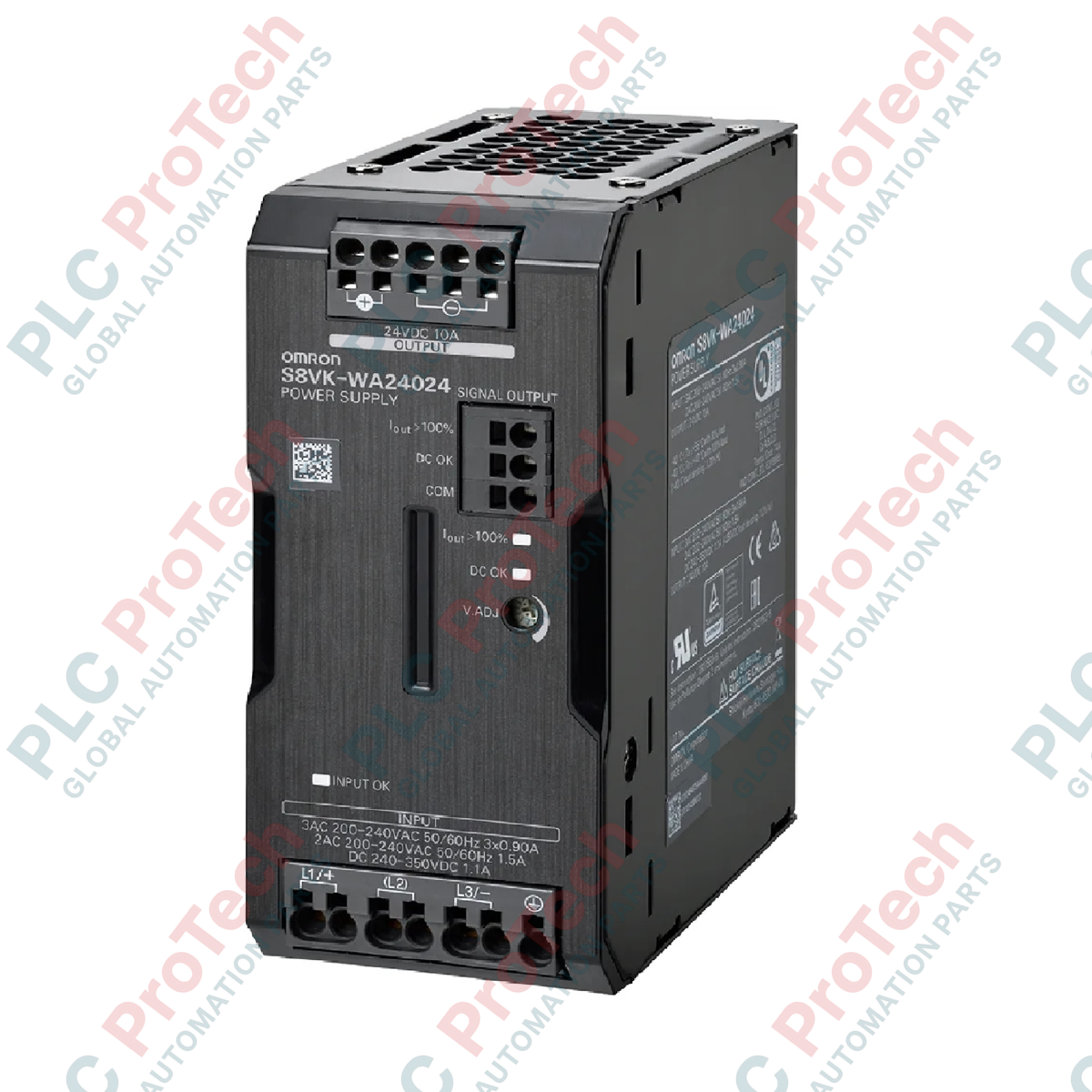
Operating as a high-efficiency electrical conversion module, the Omron S8VK-WA24024 delivers stable direct current to demanding industrial automation networks from a three-phase power source. This switch-mode power supply is engineered to mitigate phase unbalance risks and provide continuous, reliable 24 VDC output within compact control cabinets. Designed with a robust covered housing and integrating Omron's proprietary Push-In Plus terminal connection technology, the unit minimizes installation labor while maximizing resistance to physical vibrations common in heavy industrial manufacturing environments.
| Specification Parameter | Verified Engineering Value |
|---|---|
| Manufacturer | Omron |
| Model Number | S8VK-WA24024 |
| Series Name | S8VK-W |
| Rated Input Voltage | 200 to 240 VAC (Three-Phase) |
| Power Rating | 240 W |
| Rated Output Voltage | 24 VDC |
| Rated Output Current | 10 A |
| Maximum Boost Current | 15 A |
| Terminal Type | Push-In Plus Terminal Block |
| Construction Type | Covered |
| Degree of Protection | IP20 (EN/IEC 60529) |
| Unit Weight | 0.8 kg |
| Shipping Weight (Calculated) | 2.0 kg |
| Terminal Block Section | Terminal Designation | Functional Assignment |
|---|---|---|
| Input Terminals (Top) | L1 | AC Input Phase 1 |
| L2 | AC Input Phase 2 | |
| L3 | AC Input Phase 3 | |
| PE (Ground Symbol) | Protective Earth Ground (Safety Ground) | |
| Output Terminals (Bottom) | +V (1) | Positive 24 VDC Output Line 1 |
| +V (2) | Positive 24 VDC Output Line 2 | |
| -V (1) | Negative 24 VDC Output Line 1 (Return) | |
| -V (2) | Negative 24 VDC Output Line 2 (Return) |
The S8VK-WA24024 serves as a more reliable alternative to single-phase S8VK-G or S8VK-X units when deployed in facilities suffering from persistent neutral line noise or phase unbalance. Because it derives power across three balanced phases, it prevents the local neutral circuit from overheating. When substituting this unit for older legacy switch-mode models, verify the 3-phase line configuration, as this module requires a nominal input of 200 to 240 VAC to meet the rated 240W threshold.
A common mistake during panel integration is overloading the 15 A boost current duration. While the S8VK-WA24024 cleanly handles up to 150% of its rated capacity, this boost is strictly rated for temporary duty cycles. Continuous operation beyond the designated peak window will trigger thermal overcurrent protection, causing the output voltage to dip or cycle. Ensure the control cabinet maintains at least 15 mm of free spacing on both side panels and 50 mm vertically to allow optimal convection cooling, as restricted air passage accelerates thermal degradation.
To ensure gas-tight connections with the Push-In Plus mechanism, strip solid conductor wires or crimped ferrules to exactly 10 mm. When introducing stranded wires without ferrules, utilize a flathead precision screwdriver to depress the orange release tab prior to inserting the wire. Avoid twisting the stranded wires to prevent individual copper strands from splaying, which can lower the effective contact cross-section and generate localized hotspot resistance.
Global Express Shipping
Returns & Warranty
Orders are processed and delivered Monday-Friday (excluding public holidays).
For full eligibility, restocking fees, and international return details, please view our official Refund & Return Policy .
| Country of origin |
Japan
|

Implement a 3-SPST switch XOR light circuit in LogixPro or RSLogix 500 using an internal relay bit. Includes truth tables, boolean equations, and verified.

Integrate Allen-Bradley CompactLogix, Caterpillar ATS, and generators into DeltaV DCS over Modbus RTU. Covers ProSoft MVI69-MCM, Miille DIN266 gateways.

ONS instruction fires but the OTE coil never latches in Studio 5000 because the one-shot is only true for one scan. Use OTL/OTU or seal-in logic instead.

Configure Allen-Bradley Kinetix 5500 servo drives on EtherNet/IP. Covers CIP Sync, IEEE 1588 V2 timing, Stratix selection, DLR topology, and HMI.

A moving-average filter is the sliding-window smoother most instrument engineers drop into DCS and PLC analog paths. Here is how the window works, how N and sample time set lag, and when a...

On Frame 5–9 gas turbines, GE Mark VI and Mark VIe run control as function-block application software. This article maps process, protection, and sequencing functions—and what Toolbox ST access...