Description
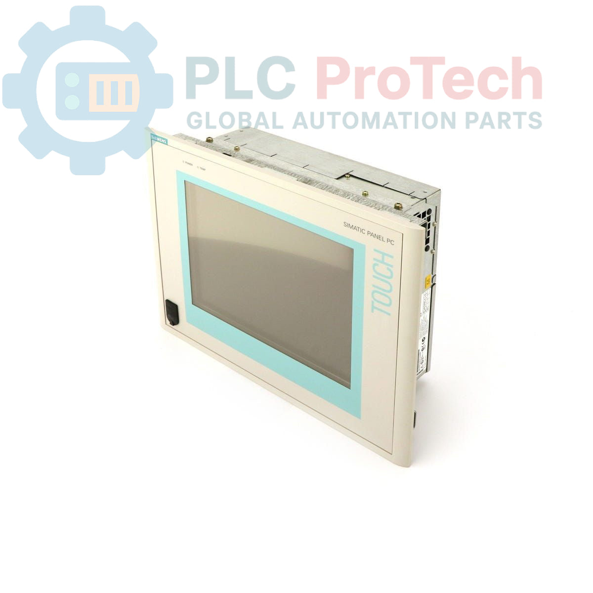
This is a Siemens SIMATIC Panel PC 670, model 6AV7611-0AB22-0CF0, designed for industrial human-machine interface (HMI) and control applications. This unit features a 10-inch TFT display and is powered by a Pentium III 500 MHz CPU. It is configured with 128 MB of RAM, a 20 GB hard drive, and a CD-ROM drive. The system is pre-installed with the Windows 98 operating system in English and is supplied with a European mains power cable for operation on 115-230V AC power sources.
Features
- 10-inch color TFT display for process visualization.
- Integrated Pentium III 500 MHz processor.
- 128 MB of system RAM.
- 20 GB hard drive for application and data storage.
- Built-in CD-ROM drive for software installation.
- Pre-loaded with Windows 98 (English).
- Supports a wide input voltage range of 115-230V AC.
Applications
- Machine-level operator control and monitoring.
- Process visualization and data acquisition (SCADA).
- Industrial data logging and recipe management.
- Factory automation control panels.
Technical Specifications
| Specification |
Value |
| Manufacturer |
Siemens |
| Series |
SIMATIC Panel PC 670 |
| Part Number |
6AV7611-0AB22-0CF0 |
| Product Type |
Panel PC |
| Display |
10-inch TFT |
| Processor (CPU) |
Pentium III 500 MHz |
| Memory (RAM) |
128 MB |
| Storage |
20 GB Hard Drive (HD) |
| Optical Drive |
CD-ROM |
| Operating System |
Windows 98 (English) |
| Input Voltage |
115-230V AC |
| Included Accessories |
European Mains Cable |
| Product Lifecycle Status |
Obsolete |
| Shipping Weight |
4.00 kg |
| Harmonized Tariff Code |
85371091 |
| ECCN |
N |
| Country of Origin |
Germany (Estimated) |
| Package Dimensions (Calculated) |
45 cm x 35 cm x 20 cm |
Installation Guidelines
CRITICAL WARNING: Electrical Shock Hazard. Disconnect and lock out all power sources before installation or servicing. Installation must be performed by qualified personnel only. Failure to comply can result in severe injury or death.
-
1
De-energize Equipment: Before beginning installation, ensure the control cabinet or mounting location is completely de-energized, locked out, and tagged out (LOTO). Verify absence of voltage.
-
2
Prepare Panel Cutout: Verify that the panel cutout dimensions match the requirements for the PC 670 chassis. Ensure the mounting surface is clean, flat, and rigid enough to support the unit's weight.
-
3
Mount the Unit: Insert the Panel PC into the cutout from the front of the panel. Secure it from the rear using the provided mounting clamps, tightening them evenly to ensure a proper seal and secure fit. Do not overtighten.
-
4
Connect Power and Ground: Connect the protective earth (PE) conductor to the designated grounding terminal on the chassis. Connect the supplied mains power cable to the unit's power input and to a properly rated and protected AC power source.
-
5
Connect Peripherals: Connect all required communication, I/O, and peripheral cables (e.g., Ethernet, keyboard, mouse). Ensure all connectors are fully seated and secured.
-
6
Final Checks and Power-Up: Close the control cabinet door. Remove the LOTO device and re-energize the main power supply. Power on the Panel PC and verify that the operating system boots correctly.