Description
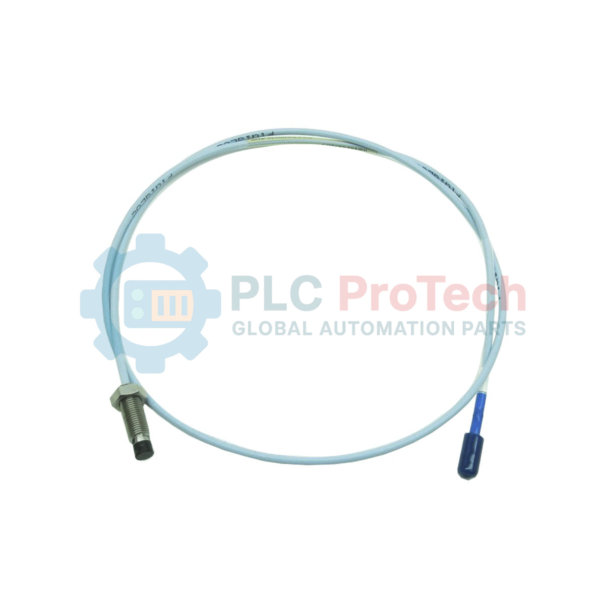
Engineered for high-reliability vibration and shaft position monitoring, the Bently Nevada 330101-00-52-10-02-CN serves as an industrial-grade non-contacting displacement sensor within the 3300 XL 8 mm Proximity Transducer System. This probe delivers continuous, accurate measurements of shaft displacement, radial vibration, and axial thrust position in critical rotating machinery, offering exceptional resistance to fluid ingress and mechanical wear.
Key Features
-
API 670 Compliance: Fully meets industry standards for machinery protection and diagnostic systems.
-
ClickLoc Connector: Features a moisture-resistant, gold-plated miniature coaxial ClickLoc connector for secure mechanical coupling.
-
Corrosion-Resistant Housing: Standard stainless steel probe case protects inner core assemblies from harsh environments.
-
Optimized Thermal Stability: Maintained signal integrity across wide temperature variations typical of heavy industrial turbine halls.
Applications
- Steam and gas turbine shaft vibration analysis.
- Thrust and radial position measurements in centrifugal compressors.
- Hydro-turbine generator shaft monitoring.
- Industrial gearbox and high-pressure pump shaft displacement sensing.
Technical Specifications
| Manufacturer |
Bently Nevada |
| Model Number |
330101-00-52-10-02-CN |
| System Compatibility |
|
Unthreaded Length Option |
0.0 in |
| Overall Case Length Option |
5.2 in (132 mm) |
| Total Length Option |
1.0 meter (3.3 feet) |
| Connector and Cable Type |
Miniature coaxial ClickLoc connector, standard cable |
| Agency Approval Option |
CN (Country-Specific Approvals) |
| Physical Weight |
0.323 kg |
| Shipping Weight |
1.500 kg |
| Country of Origin |
United States (U.S.A.) |
Empirical Engineering Insights
Alternative Models & Compatibility
This 1.0-meter probe requires strict pairing with compatible Bently Nevada components. To form a functional 5.0-meter system, it must be paired with a 4.0-meter extension cable and a 5.0-meter Proximitor Sensor. For a 9.0-meter system, utilize an 8.0-meter extension cable paired with a 9.0-meter Proximitor. Mixing system lengths (e.g., using a 9.0-meter extension cable with a 5.0-meter Proximitor) will cause severe calibration offsets and inaccurate displacement data.
Application Pitfalls & Engineering Notes
The 5.2-inch overall case length is designed for deep-well installations. When mounting this unit, calculate the casing thermal expansion under operational load. Inadequate bracket rigidity or failure to account for casing thermal growth can cause physical contact between the 8 mm tip and the rotating shaft target, leading to immediate sensor failure. Ensure signal cables are routed through dedicated grounded conduits separate from high-voltage AC lines to prevent EMI noise injection.
Commissioning & Calibration Tips
During commissioning, calibrate physical probe gapping using a digital multimeter measuring the DC voltage output at the Proximitor Sensor terminal. A physical gap of 1.0 mm (40 mils) corresponds to a standard sensor bias voltage of -10.0 VDC when calibrated against AISI 4140 steel. Before locking the mounting thread, verify that physical runout and electrical runout do not exceed API 670 guidelines (typically 0.25 mils / 6.3 micrometers combined).
Installation Guidelines
CRITICAL WARNING: SAFETY FIRST
De-energize the monitored machinery and lockout/tagout all power systems before probe adjustment. Ensure the physical rotor shaft is static before setting probe clearances. Improper physical adjustment can cause mechanical impact, leading to physical damage to both the turbine shaft and the probe assembly.
1
Clean Target Area: Verify that the probe target area on the shaft is clean, free of carbon deposits, and matches the calibration alloy (typically AISI 4140).
2
Thread Assembly: Thread the probe carefully into the bracket or casing, taking care not to twist or strain the integrated 1.0-meter coaxial cable during rotation.
3
Establish Bias Gap: Hook up a digital multimeter to the Proximitor monitor output. Adjust probe depth until the signal reads -10.0 VDC (center of linear range), then tighten locknuts to target torque specifications.
4
Secure Connections: Connect the ClickLoc miniature coaxial interface. Ensure connection is fully locked and insulate using silicone self-fusing tape or connector protectors if oil mist is present.