Description
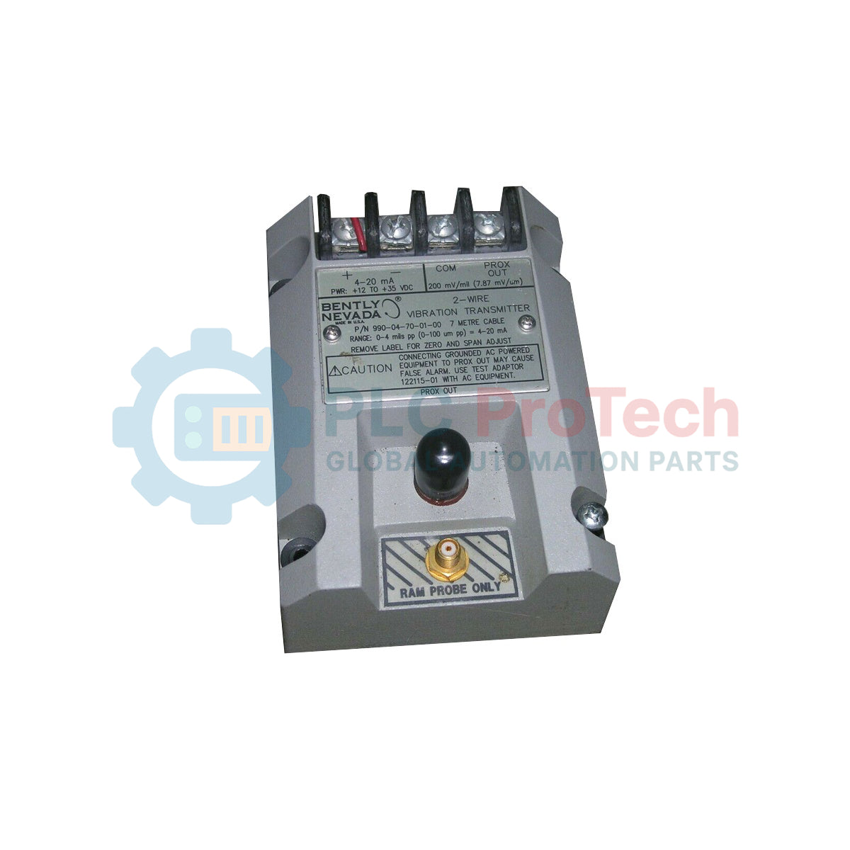
Engineered for seamless integration into industrial machinery protection systems, the Bently Nevada 990-04-70-01-CN functions as a high-precision, loop-powered sensor interface designed to continuously monitor shaft vibration. This 2-wire transmitter converts the dynamic displacement signal from a proximity probe system into a standard 4-20 mA analog current loop, facilitating direct communication with programmable logic controllers (PLCs), distributed control systems (DCSs), or machine condition monitoring platforms.
Designed for rugged industrial environments, this unit simplifies field wiring by combining the proximitor sensor electronics and transmitter functionality into a single, compact housing. The 990-04-70-01-CN is factory-configured for a 0-4 mils peak-to-peak measurement range, optimized for a 7.0-meter system length, and equipped with quick-install DIN rail mounting clips.
Key Features
-
Integrated Proximitor Design: Merges proximity probe driver circuitry with 4-20 mA transmitter loops to minimize total component count in monitoring panels.
-
Loop-Powered 2-Wire Interface: Reduces wiring costs and installation complexity by utilizing the same pair of conductors for both signal transmission and operating power.
-
Non-Contacting Displacement Measurement: Interfaces with standard eddy current proximity probes to measure dynamic shaft movement without physical contact.
-
Local Buffered Output: Provides a raw dynamic signal via a coaxial connector for diagnostic access and vibration analysis with portable instruments.
-
High Noise Immunity: Robust shielding and isolation prevent electromagnetic interference in high-power motor and turbine environments.
Applications
- Radial vibration monitoring on centrifugal air and gas compressors.
- Casing and shaft vibration monitoring of industrial steam and gas turbines.
- Overhung fan shaft displacement tracking in cooling towers.
- Continuous condition monitoring of heavy-duty process pumps.
- Balance-of-plant rotating machinery protection where full rack systems are not required.
Model Suffix Configuration
| Suffix Code |
Option Class |
Technical Specification |
| -04 |
Full-Scale Range |
0 to 4 mils pp (0 to 100 micrometers peak-to-peak) |
| -70 |
System Length |
7.0 meters (23.0 feet) total electrical length |
| -01 |
Mounting Hardware |
35 mm DIN rail clips pre-installed |
| -CN |
Agency Approvals |
Region-specific safety certifications (China/Asia-Pacific) |
Technical Specifications
| Manufacturer |
Bently Nevada |
| Model Series |
990 Vibration Transmitter Series |
| Full-Scale Input Range |
0 to 4 mils peak-to-peak (0 to 100 um pp) |
| Output Signal Range |
4 to 20 mA DC (proportional to full scale) |
| Operating Voltage |
12 to 35 VDC (at the transmitter terminal) |
| Maximum Loop Resistance |
RLoop = (VSupply - 12V) / 0.02A ohms |
| Required Probe Compatibility |
3300 XL 8mm proximity probe (or verified equivalent) |
| Target Calibration Material |
AISI 4140 steel (standard target configuration) |
| Operating Temperature Range |
-35 to +85 Celsius |
| Storage Temperature Range |
-40 to +100 Celsius |
| Country of Origin |
United States |
| Shipping Weight (Calculated) |
1.5 kg (approx. 3.3 lbs) |
Connections and Interfaces
| Terminal / Port |
Label / Standard Marker |
Function & Circuit Assignment |
| Pin 1 |
+ / PWR |
Positive supply voltage connection (4-20 mA Loop +) |
| Pin 2 |
- / SIG |
Signal return connection (4-20 mA Loop -) |
| Pin 3 |
SHD |
Instrumentation shield tie-point (internally isolated from DIN rail) |
| Coaxial Port |
BUF |
Coaxial buffered raw voltage output (approx. 7.87 V/mm scale) |
Empirical Engineering Insights
Alternative Models & Compatibility
The 990-04-70-01-CN requires an absolute electrical system length match of 7.0 meters. Do not mix and match with 5.0-meter probe configurations (such as the -50 options) or non-3300 XL systems without recalibrating, as mismatching will cause extreme signal non-linearity and scale factor errors.
Application Pitfalls & Engineering Notes
In highly active electromagnetic environments (e.g., adjacent to variable frequency drives), a common error is allowing the transmitter housing to float electrically. Ensure the 35 mm DIN rail has a direct, low-impedance ground path. Additionally, calculate loop resistance strictly using the minimum expected voltage supply at the cabinet to prevent transmitter dropout at full-scale signal levels (20 mA peaks).
Commissioning & Wiring Tips
When wiring the coaxial sensor extension cable, protect the connector with self-fusing silicone tape or heat-shrink tubing to prevent moisture ingress. Liquid intrusion at the probe-to-extension cable joint alters loop impedance, showing up on the DCS as false high vibration or erratic signal spikes.
Installation Guidelines
CRITICAL SAFETY WARNING
Before installing, removing, or performing maintenance on the transmitter, de-energize all connected electrical loops. Ensure the ambient atmosphere is certified non-hazardous or that proper intrinsically safe barriers are active if deploying this -CN model in classified field areas.
1
Mount the unit firmly onto standard 35 mm symmetric DIN rail (EN 50022) using the integrated -01 mounting clips. Ensure the rail is bonded to a noise-free industrial ground.
2
Connect the 7.0-meter proximity probe coaxial cable system to the integrated coaxial input connector on the transmitter. Hand-tighten the coupling, then snug-tighten to prevent vibration loosening.
3
Route a shielded, twisted-pair instrument cable from the 4-20 mA loop controller to the transmitter terminal block. Terminate +PWR to Pin 1, -SIG to Pin 2, and the cable shield to Pin 3 (SHD).
4
Apply loop power (typically 24 VDC) and verify quiescent loop current draws approximately 4 mA under static (no-vibration, gapped probe) conditions.