Description
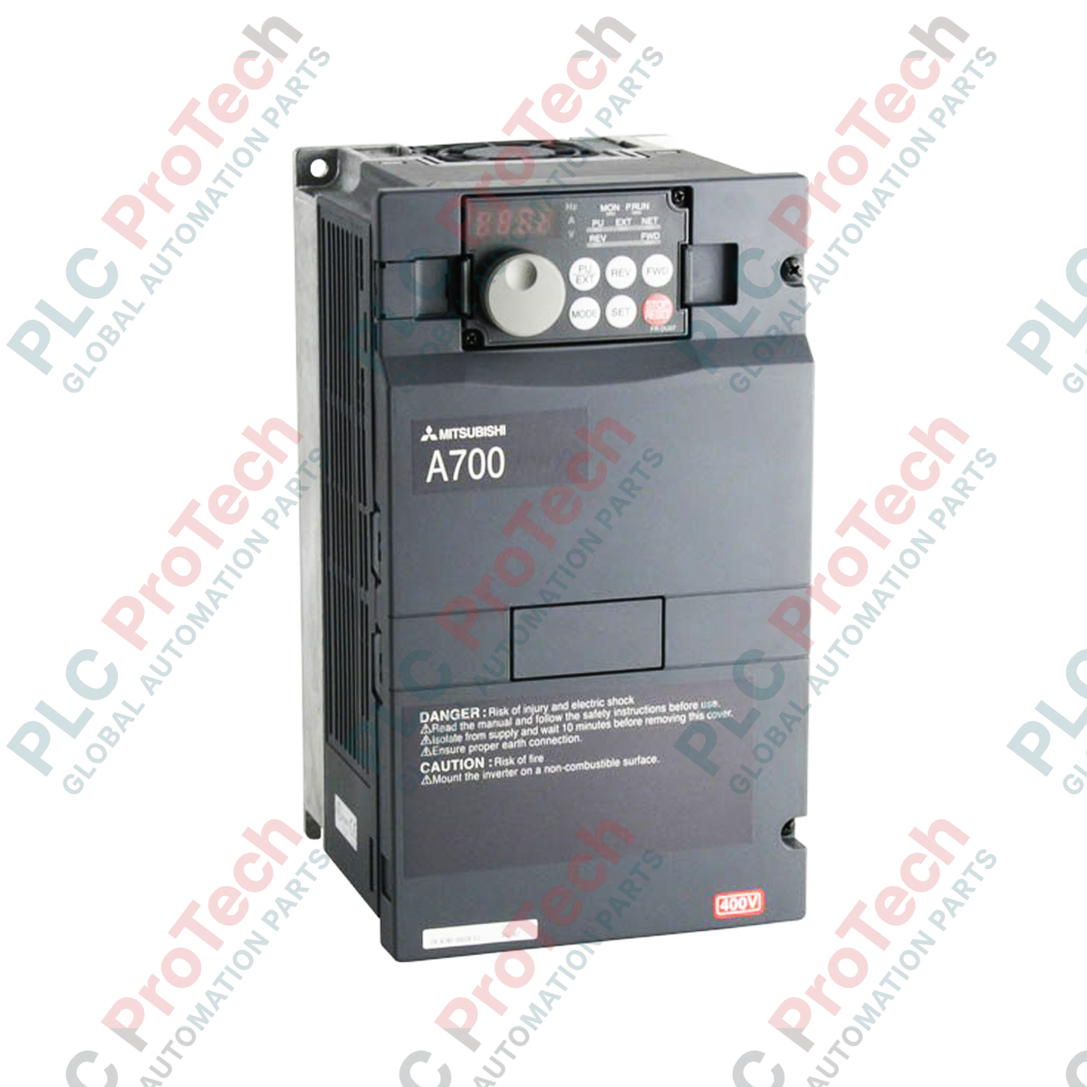
Providing high-performance vector control for heavy-duty industrial applications, the Mitsubishi Electric FR-A740-15K frequency inverter delivers precise motor regulation across demanding operational profiles. This variable frequency drive (VFD) from the FR-A700 Series is engineered for complex systems requiring high torque, exceptional speed accuracy, and advanced motor control dynamics. Operating on a 400V class three-phase input, it handles a nominal motor output of 15 kW, making it a reliable component in heavy machinery, extrusion lines, cranes, and continuous manufacturing systems.
Equipped with Real Sensorless Vector (RSV) control and advanced vector control algorithms, the drive achieves outstanding speed and torque performance without requiring encoder feedback. The integrated PLC functionality allows users to customize control sequences directly within the inverter, reducing external hardware overhead and simplifying system integration.
Features
-
Real Sensorless Vector Control: Achieves high torque at ultra-low speeds (200% at 0.3 Hz) for high-inertia start-up profiles.
-
Optimum Excitation Control: Automatically adjusts the excitation current to maximize motor efficiency, reducing energy consumption under partial loads.
-
Built-in PLC Programming: Enables customized logic and automated control loops via Mitsubishi's software environment, bypassing the need for an external micro-PLC.
-
Advanced Torque Limiters: Protects mechanical drivetrains with fast, highly responsive 4-quadrant torque limitation.
-
USB Port Integration: Front-mounted interface for swift configuration, diagnostics, and parameter backup using FR Configurator software.
Applications
-
Hoists and Cranes: High-starting torque and mechanical brake control linkage ensure safe and smooth vertical transitions.
-
Extruders and Mixers: Provides stable speed regulation under fluctuating viscosity loads.
-
Centrifuges and Fans: Energy-efficient operation through optimized excitation and smooth deceleration control.
-
Conveyor Networks: Precise multi-drive speed synchronization prevents physical product damage and belt wear.
Technical Specifications
| Parameter |
Value / Specification |
| Manufacturer |
Mitsubishi Electric |
| Model Number |
FR-A740-15K |
| Inverter Series |
FR-A700 |
| Voltage Class |
400V Class (Three-Phase 380 to 480 VAC, 50/60 Hz) |
| Permissible AC Voltage Fluctuation |
323 to 528 VAC (50Hz/60Hz) |
| Applicable Motor Capacity |
15 kW |
| Rated Output Current |
31 A |
| Overload Current Rating |
150% 60 seconds, 200% 3 seconds (at ambient temperature of 50 degC) |
| Cooling Method |
Forced Air Cooling |
| Enclosure Rating |
IP20 (Open Type) |
| Net Weight |
7.5 kg |
| Shipping Weight (Calculated) |
9.0 kg |
Connections and Interfaces
| Terminal Group |
Functional Assignment |
| R/L1, S/L2, T/L3 |
Main 3-phase AC power supply input terminals. |
| U, V, W |
3-phase AC output connections to the induction motor. |
| P/+, PR |
Connection terminal for optional external brake resistor. |
| STF / STR |
Forward rotation start / Reverse rotation start control terminals. |
| 10, 2, 5 |
Analog input terminals (0 to 10 VDC, 4 to 20 mA) for external frequency references. |
Empirical Engineering Insights
Alternative Models & Compatibility
When migrating or sourcing drop-in replacements, note that the FR-A740-15K shares functional equivalents within the newer FR-A840-00380-E2-60 (A800 series). Parameter transfer from the A700 to the A800 series can be automated via the FR Configurator2 software. However, verify terminal assignment modifications, as the control terminal blocks differ in wiring entry formats (screw terminals on the A700 vs. spring clamp terminals on the A800).
Application Pitfalls & Engineering Notes
If operating in high ambient conditions (above 40 degC), the carrier frequency should be adjusted downward (Parameter 72) to prevent premature thermal overcurrent faults (E.THT). Avoid continuous operation below 6 Hz without supplementary external motor cooling fan kits, as standard self-cooled motors will experience severe thermal degradation at reduced speeds due to diminished internal fan velocity.
Commissioning & Wiring Tips
Always ensure that Parameter 9 (Electronic Thermal O/L Relay) is set to match the nameplate current of the connected motor; the factory default corresponds to the maximum rating of the VFD and may fail to protect smaller motors. Install control signals using shielded twisted-pair cables with the shield grounded only at the drive end (Terminal 5) to mitigate electromagnetic interference in analog circuits.
Installation Guidelines
CRITICAL WARNING: HIGH VOLTAGE HAZARD
Isolate all input AC power before performing any terminal modifications or inspection routines. Wait a minimum of 10 minutes after physical power disconnection for the internal DC-bus capacitors to fully discharge. Verify that the DC-bus voltage between terminals P/+ and N/- is below 45 VDC using a calibrated digital multimeter before proceeding with touch operations.
1
Mount the inverter vertically inside an IP54 enclosure if the environment is dusty or humid, ensuring a minimum clearance of 10 cm above and below the unit for unobstructed heat dissipation.
2
Ensure the physical ground connection meets standard industrial safety requirements (Earth resistance under 10 ohms). Use a thick copper protective conductor connected to the drive's PE terminal.
3
Confirm that power cable routing is physically separated from control and encoder feedback signaling paths to minimize capacitive coupling noise.