Описание
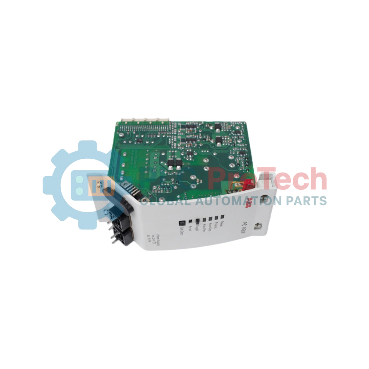
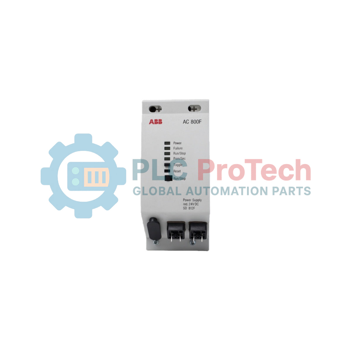
ABB SD 812F — это промышленный компонент питания на DIN-рейку, разработанный для обеспечения стабилизированного постоянного тока локальным архитектурам обработки в платформе полевой автоматизации AC 800F. Работая как специализированный источник питания, это устройство обеспечивает регулируемый выход 24 В постоянного тока, создавая стабильные электронные условия работы для модульных полевых контроллеров и подключенной трансиверной инфраструктуры.
SD 812F оптимизирован для работы в тесной координации с централизованными процессорными элементами, специально соответствуя электрическим требованиям модулей контроллеров PM 802F или PM 803F. Каталоговый номер продукта 3BDH000014R1, этот компактный интерфейс питания 24 В постоянного тока обеспечивает высокую стабильность электрической изоляции и отслеживания напряжения в промышленных сетях автоматизации, предотвращая сбои системы из-за изменений основной линии или нагрузок.
Особенности
-
Оптимизация для контроллера: Адаптирован для бесшовной интеграции в физическую компоновку и электрического согласования с узлами контроллеров PM 802F или PM 803F.
-
Стабилизированный выход 24 В постоянного тока: Обеспечивает низкопульсирующее, постоянное напряжение для защиты чувствительных логических схем от индуктивных помех питания.
-
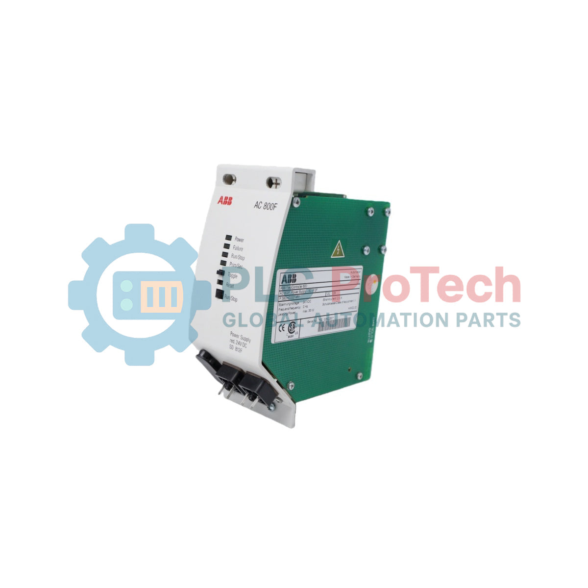
Компактный механический корпус: Спроектирован с шириной корпуса всего 67 мм для максимальной плотности монтажа на рейке в плотно укомплектованных промышленных шкафах управления.
-
Прочный корпус: Оснащен надежным шасси, разработанным для выдерживания постоянных тепловых нагрузок конвекции и вибраций оборудования.
Применение
- Основное питание локальной станции для полевых контроллеров ABB AC 800F и смежных коммуникационных шин ввода-вывода.
- Специализированная стабилизация электрической цепи внутри шкафов автоматизации процессов, распределенных систем управления (DCS) и систем удаленной телеметрии.
Технические спецификации
| Параметр |
Технические характеристики |
| Производитель |
ABB |
| Обозначение модели |
SD 812F |
| ID продукта / номер заказа |
3BDH000014R1 |
| Тип продукта |
Источник питания |
| Выходное напряжение |
24 В постоянного тока |
| Совместимость контроллера |
PM 802F / PM 803F |
| Таможенный тарифный номер |
85044030 |
| Статус типа детали |
Оригинал / Новый |
| Ширина продукта |
67 мм |
| Высота продукта |
155 мм |
| Глубина продукта |
155 мм |
| Чистый вес продукта |
0,46 кг |
| Вес при транспортировке (расчетный) |
0,68 кг |
| Размеры упаковки (расчетные) |
195 мм x 195 мм x 95 мм |
Эмпирические инженерные данные
Альтернативные модели и совместимость
SD 812F предназначен исключительно для промышленных контуров с аппаратной базой PM 802F или PM 803F. Для развертывания архитектуры управления требуется, чтобы на контроллере была установлена и активно работала версия системного программного обеспечения V7.1SP2a или выше для полной поддержки мониторинга конфигурации системы. При обновлении или замене устаревших узлов обязательно сверяйте версию прошивки базовой платформы, чтобы избежать сбоев инициализации связи по внутренней шине.
Ошибки применения и инженерные заметки
Поскольку этот блок питания использует естественную тепловую конвекцию через вертикальные зазоры корпуса, установка модуля непосредственно рядом с тепловыделяющими клеммными рейками или в непроветриваемых корпусах без достаточных зазоров может вызвать преждевременный тепловой стресс. Это приводит к снижению номинальной токовой нагрузки или спонтанному падению выходного напряжения. Держите верхние и нижние вентиляционные отверстия полностью свободными от пучков проводов и конструктивных препятствий.
Советы по вводу в эксплуатацию и проводке
Проверьте надежность механического соединения линий подачи 24 В постоянного тока для минимизации сопротивления клемм при высоких нагрузках. Проложите отдельные короткие заземляющие пути от каркаса рейки к основной медной опорной шине для устранения высокочастотных гармоник переключения и установления надежной нулевой точки общего потенциала во всех входных и выходных цепях.
Руководство по установке
КРИТИЧЕСКОЕ ПРЕДУПРЕЖДЕНИЕ: СОБЛЮДЕНИЕ ТРЕБОВАНИЙ ПО ОБЕЗЭНЕРЖИВАНИЮ ЭЛЕКТРИЧЕСТВА
Изолируйте и пометьте все первичные питающие кабели и вспомогательные ответвления перед работой или манипуляциями с клеммами. Работа с активными элементами представляет серьезную опасность поражения электрическим током и может вызвать разрушительные короткие замыкания в соседних процессорных узлах. Перед обслуживанием убедитесь в полном отсутствии напряжения на входе с помощью откалиброванного промышленного мультиметра.
1
Зафиксируйте корпус блока питания на стандартной монтажной рейке DIN 35 мм, убедившись, что интегрированный заземляющий зажим надежно и без изоляции контактирует с поверхностью рейки.
2
Подключите входные проводники переменного тока и кабели распределения 24 В постоянного тока к соответствующим клеммным зажимам согласно чертежам панели.
3
Убедитесь, что необходимые зазоры сохраняются в верхней и нижней части корпуса модуля для обеспечения свободной тепловой конвекции перед подачей питания.