Описание
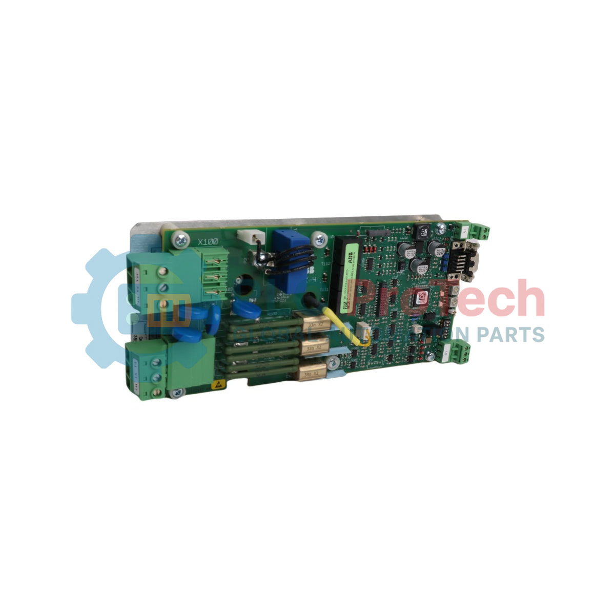
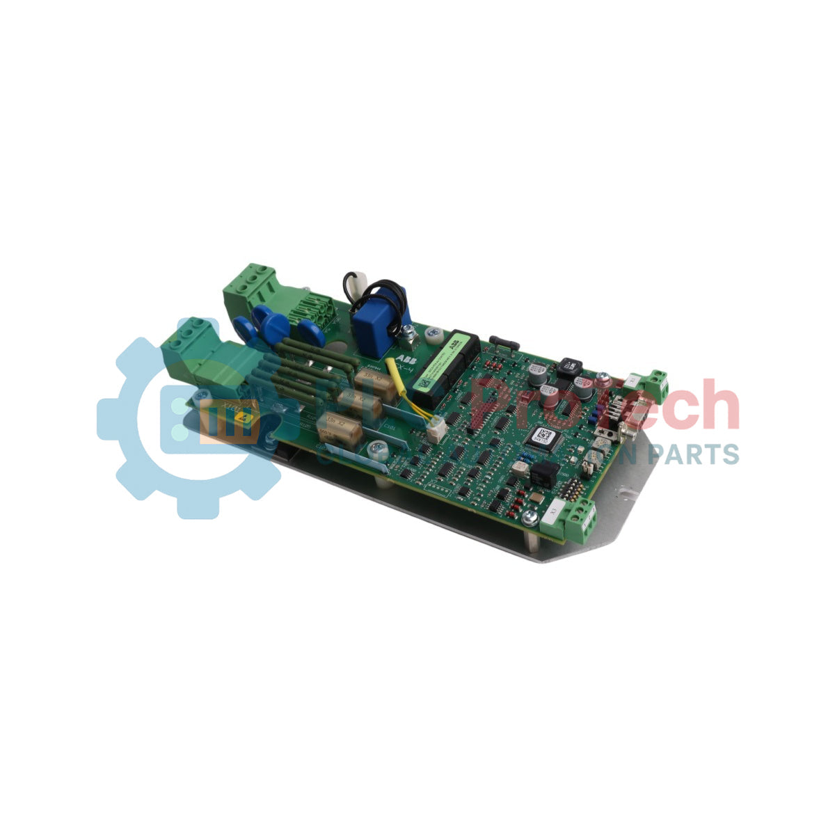
ABB SDCS-FEX-4A — интегрированный внутренний тиристорный мост, разработанный для управления коммутационными и индукционными путями напряжения внутри топологий полей приводов постоянного тока. Работая как специализированная плата возбуждения, эта электронная карта обеспечивает точное переменное регулирование тока для отдельных обмоток поля, соответствуя динамическим нагрузкам в приводах малой и средней мощности.
Сборка SDCS-FEX-4A интегрирует линии прямой синхронизации векторного управления с внутренними процессорными путями для обеспечения мгновенных обратных связей по току вычислений. Обозначенный под идентификатором продукта 3ADT314500R1501, этот внутренний модуль возбуждения поля уравновешивает отклонения питания и тепловые дрейфы в промышленных сетях обработки, обеспечивая поддержание рабочего тока и предотвращая локальное магнитное разрушение сердечника.
Особенности
-
Интегрированный тиристорный мост: Обеспечивает переменные выходные пути постоянного тока через согласованные сети фазового регулирования.
-
Встроенные цепи гашения: Подавляют коммутационные всплески и отражения помех на входных фазных линиях.
-
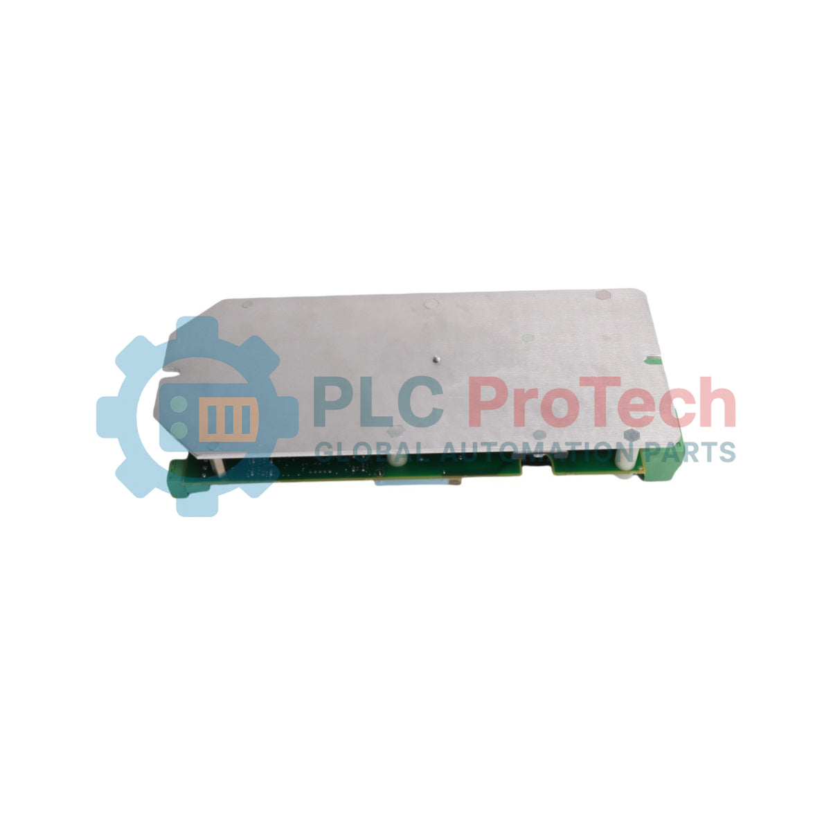
Жесткая структурная основание: Собрана на алюминиевом шасси для теплового рассеивания, предназначенном для механического крепления внутри корпусов приводов.
-
Экранированное ленточное соединение: Связывает петли векторного управления напрямую с основными процессорами регулирования двигателя.
Применения
- Замена внутреннего контроллера возбуждения поля для модульных корпусов преобразователей серии ABB DCS.
- Конфигурации динамического профилирования крутящего момента и ослабления магнитного поля для промышленных двигателей постоянного тока.
Технические спецификации
| Параметр |
Технические характеристики |
| Производитель |
ABB |
| Обозначение модели |
SDCS-FEX-4A |
| ID продукта / номер заказа |
3ADT314500R1501 |
| Диапазон входного напряжения (U1) |
3-фазный, 110 до 500 В AC |
| Максимальный входной ток (I1) |
25 A AC |
| Диапазон выходного напряжения (U2) |
0 до 500 В DC |
| Максимальный выходной ток (I2) |
25 A DC |
| Частота линии (F1) |
50/60 Hz |
| Статус типа детали |
Оригинал / Новый |
| Чистый вес продукта |
0,680 кг |
| Вес при транспортировке (расчетный) |
0,950 кг |
| Размеры упаковки (расчетные) |
255 мм x 120 мм x 50 мм |
Эмпирические инженерные данные
Альтернативные модели и совместимость
Плата SDCS-FEX-4A является прямым размерным и техническим преемником устаревших внутренних версий возбудителя поля. Она оснащена интегрированной схемой с максимальным током петли 25А, которая должна соответствовать параметрам смещения конфигурации внутри основного модуля управления. Проверьте совместимость параметров прошивки и сверяйте существующую схему ленточного кабеля привода перед установкой, так как неправильное сопоставление ограничит управление полем возбуждения.
Ошибки применения и инженерные заметки
Поскольку этот модуль возбуждения полностью полагается на естественную конвекцию через металлическую заднюю пластину, установка карты в помещениях с высокими параметрами окружающего воздуха или забитыми путями охлаждения может вызвать локальный тепловой пробой в переходах тиристоров. Такой пробой часто приводит к нерегулярным индукционным полям или неожиданным срабатываниям по превышению тока возбуждения. При регулярном обслуживании убедитесь, что изоляционные барьеры клемм не загрязнены проводящим сажей или жиром.
Советы по пусконаладке и подключению
При замене этого узла убедитесь, что разъем вспомогательного ленточного кабеля надежно зафиксирован в соответствующем слоте разъема. Ослабленные контакты могут привести к отсутствию импульсов на затворы, вызывая внезапный отказ возбуждения или фазовые дисбалансы при больших нагрузках на двигатель. Экранируйте все внешние силовые кабели, идущие к полевым клеммам, чтобы они не пересекались с высокошумными линиями обратной связи энкодера или данными, во избежание индуктивных наводок.
Руководство по установке
КРИТИЧЕСКОЕ ПРЕДУПРЕЖДЕНИЕ: ОПАСНОСТЬ ВЫСОКОВОЛЬТНОГО РАЗРЯДА
Изолируйте все входящие линии питания, фазовые соединения и вспомогательные управляющие линии, подающие питание на преобразователь, перед началом обслуживания. Подождите не менее 15 минут, чтобы внутренние конденсаторы шины полностью разрядились. Используйте проверенный вольтметр, чтобы убедиться, что все входящие и полевые клеммы полностью обесточены.
1
Наденьте заземленный антистатический браслет, чтобы защитить тиристорные затворы и логические компоненты на плате от электростатических повреждений.
2
Отключите основные клеммы полевого терминала и извлеките многоконтактный логический ленточный разъем из разъемов платы.
3
Ослабьте крепежные элементы шасси, замените пластину возбуждения на новый узел и надежно закрепите все монтажные детали для обеспечения правильного теплового контакта.