Description
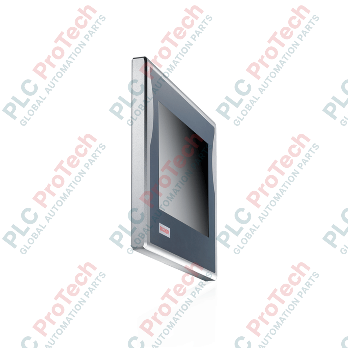
Designed for direct installation on a mounting arm, the Beckhoff CP7712-0001-0040 integrates high-performance computing capabilities into a robust, fully enclosed operator interface. Featuring a brilliant 15-inch TFT display with a native resolution of 1024 x 768 pixels, this unit is engineered to deliver reliable visualization and control in high-vibration, space-constrained industrial environments. Encased in a durable, fully sealed aluminum housing, it provides comprehensive dust and liquid resistance without requiring a separate control cabinet or protective enclosure.
Key Features
-
All-Round Protection: Sealed aluminum chassis provides IP65 rating on all sides, eliminating the need for integration into protective control cabinets.
-
Industrial Processing Core: Driven by an energy-efficient dual-core processor platform optimized for real-time control applications and human-machine interface (HMI) rendering.
-
Flexible Installation: Integrated rear mounting arm adapter equipped with four M6 threaded connections for mechanical stability and vibration resistance.
-
Sealed External Interfaces: High-reliability IP65-rated connections, including gigabit Ethernet and serial ports, ensuring secure data transmission under challenging field conditions.
Applications
-
Machine-Mount Interfaces: Direct integration onto CNC machines, robotic cells, and packaging lines.
-
Food & Beverage Processing: Deployable in environments requiring routine washdowns and strict particulate sealing.
-
Automotive Assembly Lines: Overhead mounting arm visualization units for cycle monitoring and operator dispatch.
Technical Specifications
| Parameter |
Specification |
| Manufacturer |
Beckhoff Automation |
| Model Reference |
CP7712-0001-0040 |
| Display Size |
15-inch diagonal TFT |
| Native Resolution |
1024 x 768 pixels |
| Processor |
Intel Atom x5-E3930 (1.3 GHz, 2 Cores) |
| System Memory |
4 GB DDR4 RAM |
| Storage Media |
40 GB CFast Card |
| Network Interfaces |
2 x 10/100/1000BASE-T (IP65 circular connections) |
| Serial Connection |
1 x RS232 (12-pin DIN IP65 socket) |
| Operating System |
Windows 10 IoT Enterprise |
| Input Voltage |
24 V DC |
| Ingress Protection |
IP65 (fully sealed unit) |
| Operating Temperature |
0 to 45 degC (ambient) |
| Mounting Thread Dimensions |
4 x M6 x 18 mm (on backplane) |
| TwinCAT Compatibility |
TwinCAT 3 Runtime (Performance Class 40) |
| Shipping Weight (Calculated) |
9.00 kg (19.84 lbs) |
Connections and Interfaces
| Connection / Port |
Interface Type |
Sealing Level |
| Ethernet Ports (LAN 1 / LAN 2) |
RJ45 via IP65 protective housing connector |
IP65 mated |
| Serial Port COM1 |
12-pin circular DIN (requires adapter to D-sub 9-pin) |
IP65 mated |
| Power Input |
3-pin circular screw terminal (24 V DC) |
IP65 mated |
Empirical Engineering Insights
Alternative Models & Compatibility
The CP7712-0001-0040 belongs to the CP77xx control panel generation. While sharing mounting profiles with older CP7712 units, the -0040 suffix denotes the modern dual-core Intel Atom x5-E3930 platform. Upgrading legacy systems equipped with single-core processors to this model requires ensuring TwinCAT runtime licenses are updated, as this hardware shifts the license tier to Performance Class 40 (TC3: 40).
Application Pitfalls & Engineering Notes
Because this is a fully sealed IP65 unit without an internal active cooling fan, all thermal dissipation occurs passively through the outer aluminum fins. When operating at continuous high CPU load, avoid enclosing the rear plate or placing the unit in close proximity to radiating heat sources. Maintain a minimum clear boundary of 100 mm around the housing to avoid thermal throttling above 45 degC ambient environments.
Commissioning & Wiring Tips
Always use high-flexibility Ethernet cables equipped with the correct Beckhoff IP65 strain-relief collars. Standard RJ45 patch cables will not seal properly against the chassis port, exposing internal pins to condensation. Ensure that the 24 V DC power line is properly grounded to the mechanical mounting arm to eliminate capacitive coupling from nearby variable frequency drives (VFDs).
Installation Guidelines
CRITICAL WARNING: Prior to mounting or wiring the panel, isolate and verify de-energization of the primary 24 V DC feed. Failure to completely isolate the power supply during mounting can cause electrical arc discharge, leading to transceiver degradation or damage to the integrated motherboard interfaces.
1
Align the rear mounting plane with the interface plate of the mounting arm system, ensuring the load rating is capable of supporting the static 9.0 kg weight of the PC.
2
Install four M6 bolts through the mounting arm into the threaded backplane holes. Tighten to a torque specification of 3.5 Nm to prevent detachment due to machine vibration.
3
Insert and secure the 24 V DC power connector, tightening the outer threaded collar until fully seated to guarantee the IP65 seal.
4
Connect the IP65 Ethernet interface cables and verify that all unused connector ports are covered with their respective protective sealing caps.