Description
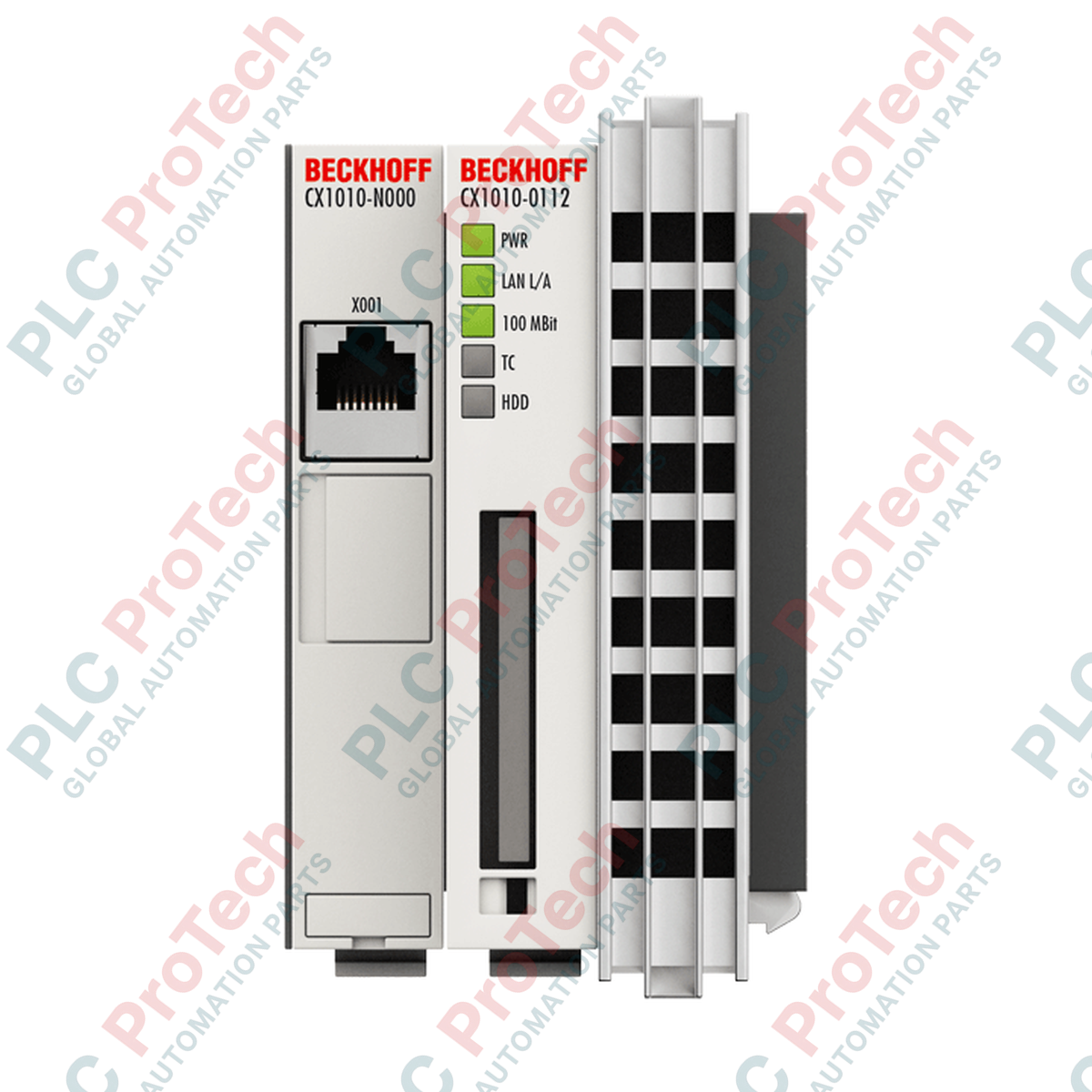
Architected as the central processing unit for modular control environments, the Beckhoff CX1010-0122 system module integrates an Intel Pentium MMX-compatible processor running at 500 MHz to handle basic PLC and motion control execution. This module functions as the execution core within a DIN-rail mounted control cluster, offering robust performance for legacy industrial networks and machine-level control systems. Equipped with 256 MB of non-expandable DDR RAM and an active Compact Flash Type II expansion slot, the CPU delivers deterministic processing capabilities when integrated with TwinCAT software control architectures.
Features
-
High-Efficiency Execution: Equipped with a 500 MHz Pentium MMX-compatible processor tailored for entry-level PLC and basic NC tasks.
-
Compact Storage: Features an accessible Compact Flash Type II slot with an integrated ejector, packaged with a 128 MB CF card.
-
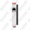
Ethernet Connectivity: Built-in 10/100 Mbit/s RJ45 port for direct industrial networking and programming access.
-
Comprehensive Diagnostics: Five local LEDs provide direct hardware feedback for power, network speed, activity, TwinCAT status, and flash card access.
-
Flexible Bus Compatibility: Interfaces with K-bus, E-bus, and IP-Link I/O systems via compatible power supply modules.
Applications
- Machine tool control and small-scale automation lines.
- Building automation substations and HVAC management systems.
- Material handling, sorting systems, and conveyor line control.
- Legacy system migration and drop-in replacements for older CX series control racks.
Technical Specifications
| Parameter |
Specification |
| Manufacturer |
Beckhoff |
| Model Number |
CX1010-0122 |
| Processor |
Intel Pentium MMX compatible, 500 MHz |
| Number of Cores |
1 |
| Main Memory |
256 MB DDR RAM (non-expandable) |
| Flash Memory |
Compact Flash Type II slot (128 MB CF card included) |
| Network Interfaces |
1 x RJ45 10/100 Mbit/s |
| System Bus Link |
16-bit ISA (PC/104) |
| Power Supply |
Via system bus (through connected CX1100-xxxx modules) |
| Max. Power Consumption |
8 W |
| Diagnostic Indicators |
1 x power, 1 x LAN speed, 1 x LAN activity, 1 x TC status, 1 x flash access |
| Internal Clock |
Battery-backed clock for date and time (battery replaceable) |
| Operating System |
Windows Embedded CE 6 / Windows Embedded Standard 2009 |
| Control Software |
TwinCAT 2 PLC runtime or TwinCAT 2 NC PTP runtime |
| Protection Rating |
IP20 |
| Operating Temperature |
0 to +50 degC |
| Storage Temperature |
-25 to +85 degC |
| Relative Humidity |
95%, non-condensing |
| Vibration/Shock Resistance |
Conforms to EN 60068-2-6 / EN 60068-2-27 |
| Approvals/Markings |
CE, UL |
| Dimensions (W x H x D) |
58 mm x 120 mm x 91 mm |
| Net Weight |
Approx. 355 g |
| Shipping Weight (Calculated) |
3.0 kg (including protective packaging) |
Empirical Engineering Insights
The hardware architecture of this CPU module demands specific maintenance considerations and configuration knowledge to ensure uninterrupted operation in industrial installations.
Alternative Models & Compatibility
This CPU module belongs to the legacy CX1010 hardware line. When replacing an older generation unit, verify your TwinCAT 2 license keys, as they are hard-coded to the unique System ID of the CPU. Upgrading to the higher-performance CX1020 or CX5100 series will require physical dimension adjustments on the DIN rail and project migration within TwinCAT 2.
Application Pitfalls & Engineering Notes
The module relies on entirely passive, fanless cooling. To prevent thermal throttling under high CPU utilization, do not block the air vents on the top and bottom of the housing. Maintain a minimum vertical clearance of 30 mm inside the electrical enclosure. Additionally, ensure that only SLC-type (Single-Level Cell) Compact Flash cards are used for the OS partition, as multi-level cell cards can experience premature failure due to continuous OS read/write cycles.
Commissioning & Wiring Tips
This CPU has no direct power terminals on its faceplate. It relies entirely on a connected CX1100-xxxx series power supply module. Ensure that the PC/104 system bus connector pins are straight and clean before joining the CPU to the power supply module. Misaligned pins during assembly can cause immediate system bus failure or permanent damage to the CPU motherboard when energized.
Installation Guidelines
CRITICAL WARNING: Never mount, demount, or adjust connections on the CPU assembly while the system is powered. Ensure all supply lines to connected CX1100 power supply modules and associated I/O modules are completely de-energized to prevent current spikes and potential system bus destruction.
1
Position the CPU module onto the 35 mm DIN rail next to the corresponding CX1100 power supply module, ensuring the PC/104 connectors align precisely.
2
Firmly push the modules together until they click into place on the rail, securing the mechanical latch to prevent shifting.
3
Insert the pre-configured Compact Flash card containing the system software into the Type II slot before initiating power-on sequence.
4
Connect the RJ45 industrial Ethernet cable to the native port to establish communications, then apply power via the main supply module.