Description
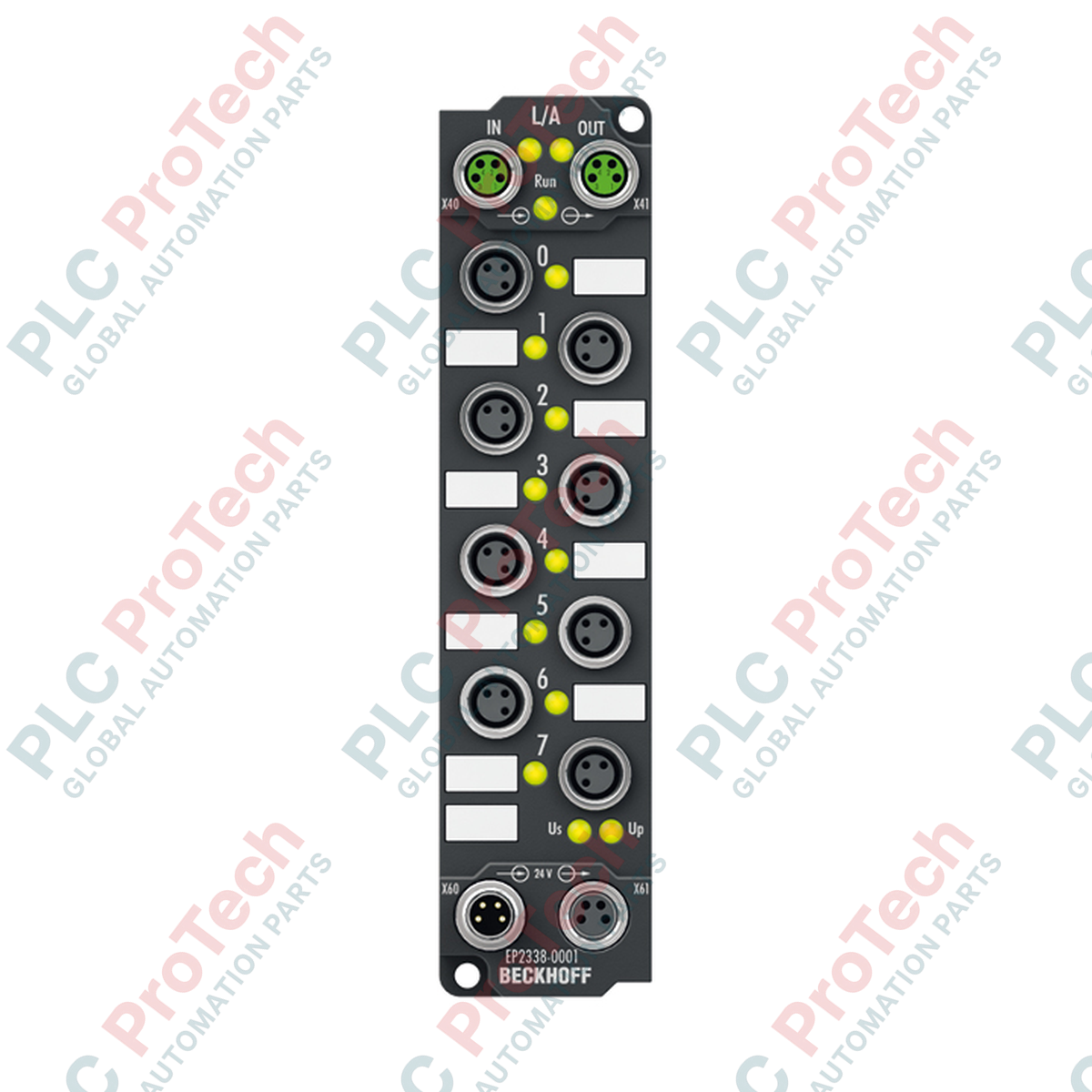
Engineered for direct machine-mount deployment, the Beckhoff EP2338-0001 EtherCAT Box offers decentralized I/O processing in a robust, compact form factor. This module features 8 digital channels that are individually and freely configurable as either inputs or outputs, optimizing field-level signal distribution without requiring intermediate terminal boxes. Operating over the native EtherCAT protocol, it interfaces via shielded, screw-type M8 bus connections, ensuring high-speed data transmission and determinism in high-vibration applications. Housed in a polyamide PA6 enclosure, it provides comprehensive protection against dust, water jets, and temporary immersion, making it suitable for wet or dirty manufacturing environments.
Features
-
Configurable I/O Flexibility: 8 channels that can be dynamically designated as digital inputs (Type 1/3) or digital outputs (0.5 A per channel).
-
Ruggedized Industrial Design: Encased in PA6 polyamide housing with IP65, IP66, and IP67 ratings for wet, dusty, or washdown conditions.
-
Direct EtherCAT Bus Interface: Dual-channel M8 connection with built-in shielding to maintain signal integrity over distributed topologies.
-
Short-Circuit Protection: Individually short-circuit proof outputs with active current-limiting and automatic recovery.
-
Hazardous Location Certification: ATEX Zone 2/22 (II 3 G Ex nA IIC T4 Gc) rated for safe installation in explosive environments.
Applications
- Decentralized conveyor control and sorting systems.
- Automotive assembly lines and robotic end-of-arm tooling.
- Packaging machinery requiring distributed IP67-rated sensor/actuator integration.
- Process plants and chemical environments requiring ATEX Zone 2 field modules.
Technical Specifications
| Parameter |
Specification Value |
| Manufacturer |
Beckhoff Automation |
| Model Identifier |
EP2338-0001 |
| Communication Protocol |
EtherCAT |
| Number of Channels |
8 digital inputs or outputs, bidirectional |
| Input Specification |
EN 61131-2, Type 1/3 (10 microsecond filter) |
| "0" Signal Voltage |
-3 to +5 V |
| "1" Signal Voltage |
11 to 30 V (6 mA nominal current) |
| Sensor Supply Current |
Max. 0.5 A total from load supply, short-circuit proof |
| Nominal Load Voltage |
24 V DC (-15% / +20%) |
| Max. Output Current |
0.5 A per channel (short-circuit proof, typical 1.5 A peak limit) |
| Switching Delays |
TON: 50 microseconds (typ.), TOFF: 100 microseconds (typ.) |
| Current Consumption |
120 mA from US (system voltage) |
| Electrical Isolation |
500 V (channel-to-logic) |
| Enclosure Material |
Polyamide PA6 |
| Protection Rating |
IP65/66/67 (conforms to EN 60529) |
| Operating Temperature |
-25 to +60 degC |
| Physical Dimensions |
30 mm x 126 mm x 26.5 mm (W x H x D) |
| Net Weight |
165 g |
| Shipping Weight (Calculated) |
0.50 kg |
Connections and Interfaces
| Interface Connection |
Connector Type |
Configuration Detail |
| EtherCAT Bus Input/Output |
2 x M8 socket (shielded, screw connection) |
Provides physical-layer uplink/downlink communication for EtherCAT frame processing. |
| Channel Interfaces |
8 x M8 x 1, 3-pin (a-coded) |
Configured dynamically via controller for physical sensor or actuator connection. |
| Power Feed |
1 x M8 male connector, 4-pin |
Input for system/sensor voltage (US) and actuator/load voltage (UP). |
| Power Downstream |
1 x M8 female connector, 4-pin |
Provides daisy-chained supply lines for downstream EtherCAT Box nodes. |
Alternative Models & Compatibility
For installations using larger cabling architectures, the EP2338-0002 features the same internal electrical logic as the EP2338-0001 but uses M12 circular connectors instead of M8. When transitioning systems from older non-EtherCAT topologies, this model directly replaces legacy Profibus or CANopen boxes. Ensure that TwinCAT 2.11 (or higher) XML configuration files are updated to map the correct hardware revision to prevent mismatch errors during system startup.
Application Pitfalls & Engineering Notes
A critical parameter during deployment is the sensor supply limit of 0.5 A total across all channels. If multiple heavy-draw inductive sensors or photo-eyes are fed from the same unit, ensure their combined quiescent and peak operational current does not exceed this limit. Overcurrent conditions will cause the sensor power rail (derived from US) to trip, resulting in field offline errors in TwinCAT. Additionally, although the outputs are protected against inductive load energy, fast-cycling inductive solenoids should be installed with external suppression elements to prolong the lifetime of the switching driver circuits.
Commissioning & Wiring Tips
Always ensure that the M8 fieldbus and power connections are torqued to the manufacturer-specified 0.4 Nm. Under-tightening compromises the IP67 moisture seal, while over-tightening can crack the polyamide housing or damage internal thread inserts. When integrating into electrically noisy environments (such as near large variable frequency drives), the mounting plate of the module should have a low-impedance ground connection. Use a serrated washer on at least one of the M3 mounting screws to bite through anodized or painted backplates and establish a reliable path to earth ground.
Installation Guidelines
CRITICAL WARNING:
De-energize all system and load power supplies (US and UP) before physically mounting or mating cables with the EtherCAT Box. Hot-plugging fieldbus or power connections in Zone 2 hazardous locations can result in electrical arcing, posing severe explosion hazards and risking immediate destruction of the unit's internal microprocessor.
1
Position the module on a flat, vibration-free surface. Mark and drill two mounting holes with a diameter of 3.5 mm to match the integrated fixing points spaced along the housing length.
2
Secure the unit using two standard M3 screws. Ensure proper grounding by establishing metallic contact between the mounting plate and the machine chassis.
3
Attach and tighten the incoming and downstream EtherCAT M8 cables. Seal unused M8 ports with protective plastic caps to maintain the IP67 ingress rating.
4
Connect the M8 auxiliary power cables, verifying that the input voltage for both US (system) and UP (actuator load) is strictly within the allowed range of 24 V DC (-15% / +20%).