Description
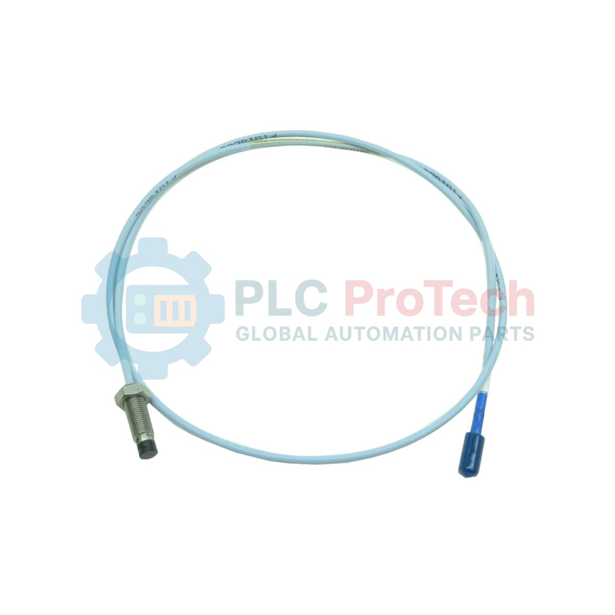
Engineered for precise dynamic and static distance measurements within critical rotating machinery, the Bently Nevada 330102-20-73-05-02-CN is an industrial-grade 3300 XL series 8 mm proximity probe. Operating as a core component of a non-contacting eddy current sensor system, this probe delivers reliable shaft vibration, position, and speed feedback for turbomachinery diagnostics. This specific model features a 3/8-24 UNF threaded body, integrated stainless steel fluid-tight armor, a 2.0-inch unthreaded length, a 7.3-inch overall case length, a 0.5-meter total cable length, and standard ClickLoc miniature coaxial connectors. Designed with specialized agency approvals for specific regional environments, it ensures exceptional longevity and resistance to aggressive industrial lubricants and harsh chemical environments.
Key Features
-
8 mm Probe Tip: Optimized for standard Bently Nevada proximity transducer systems with balanced magnetic field distribution.
-
Rugged Stainless Steel Armor: Shielded outer casing protects internal coaxial conductors from mechanical cuts, abrasions, and hot oil splashes.
-
ClickLoc Coaxial Connector: Features a gold-plated brass body with a positive locking mechanism to prevent loose connections in high-vibration panels.
-
Fluid-Tight Construction: Polyphenylene sulfide (PPS) tip material resists degradation from synthetic lubricants, water, and process chemicals.
Applications
- Radial vibration monitoring on high-speed hydrodynamic journal bearings.
- Axial thrust position measurement on steam/gas turbines and centrifugal compressors.
- Phase reference and keyphasor speed measurements on industrial gearboxes.
- Eccentricity monitoring on large generators and utility-scale pumps.
Technical Specifications
| Parameter |
Value |
| Manufacturer |
Bently Nevada |
| Model Code |
330102-20-73-05-02-CN |
| Series |
3300 XL 8 mm |
| Thread Size |
3/8-24 UNF |
| Unthreaded Length |
2.0 inches (Option 20) |
| Overall Case Length |
7.3 inches (Option 73) |
| Total Length |
0.5 meter / 1.6 feet (Option 05) |
| Connector Type |
Miniature Coaxial ClickLoc, Standard Cable (Option 02) |
| Agency Approval |
Country-Specific / China Ex & RoHS (Option CN) |
| Operating Temperature Range |
-51 to +177 degC |
| Shipping Weight (Calculated) |
2.0 kg |
| Package Dimensions (Calculated) |
250 x 200 x 60 mm |
Connections and Interfaces
| Connection Element |
Function / Assignment |
| Center Conductor |
RF signal path / high-frequency eddy current return |
| Outer Shield |
Signal common and coaxial noise shield |
| ClickLoc Outer Sleeve |
Mechanical connection locking to extension cable |
Empirical Engineering Insights
Alternative Models & Compatibility
This 0.5-meter probe is configured specifically to pair with standard 4.5-meter or 8.5-meter extension cables to complete overall system lengths of 5.0 meters or 9.0 meters. Substituting an unarmored 330101 series probe in an environment that requires armor will lead to premature cable failure due to routing friction or cutting. Ensure the Proximitor sensor calibration matches the total electrical system length (5m vs 9m).
Application Pitfalls & Engineering Notes
Keep the minimum static bend radius of the armored cable above 25 mm (1.0 inch). Bending the cable past this point risks breaking the inner coaxial shielding, resulting in high noise-to-signal ratios or intermittent readings. Additionally, ensure a minimum of 16 mm (twice the tip diameter) of lateral clearance from surrounding structural metal to prevent side-view eddy current interference.
Commissioning & Wiring Tips
Before powering up the system, use a calibrated digital multimeter to verify the resistance between the probe tip center pin and the outer shield (typically 5.0 to 11.0 ohms, depending on cable temperature). Always clean the coaxial connectors with isopropyl alcohol before mating them to ensure oil residues do not compromise the RF path.
Installation Guidelines
CRITICAL WARNING: Ensure the machinery has been fully shutdown and all power supply lines to adjacent field devices are isolated before initiating probe installation. Static charge accumulation on rotating components must be fully discharged prior to mounting.
1
Mount the probe bracket securely in the housing, ensuring the 3/8-24 UNF threaded hole aligns perfectly perpendicular to the target shaft area.
2
Thread the probe into the mounting bracket while using a gap meter or monitoring the output voltage at the Proximitor sensor terminal block to achieve the precise voltage offset representing your physical air gap (typically -10 VDC).
3
Tighten the locknut to the OEM specified torque limit. Secure the armored cable route with non-magnetic conduit clips, avoiding sharp bends or structural pinch points.