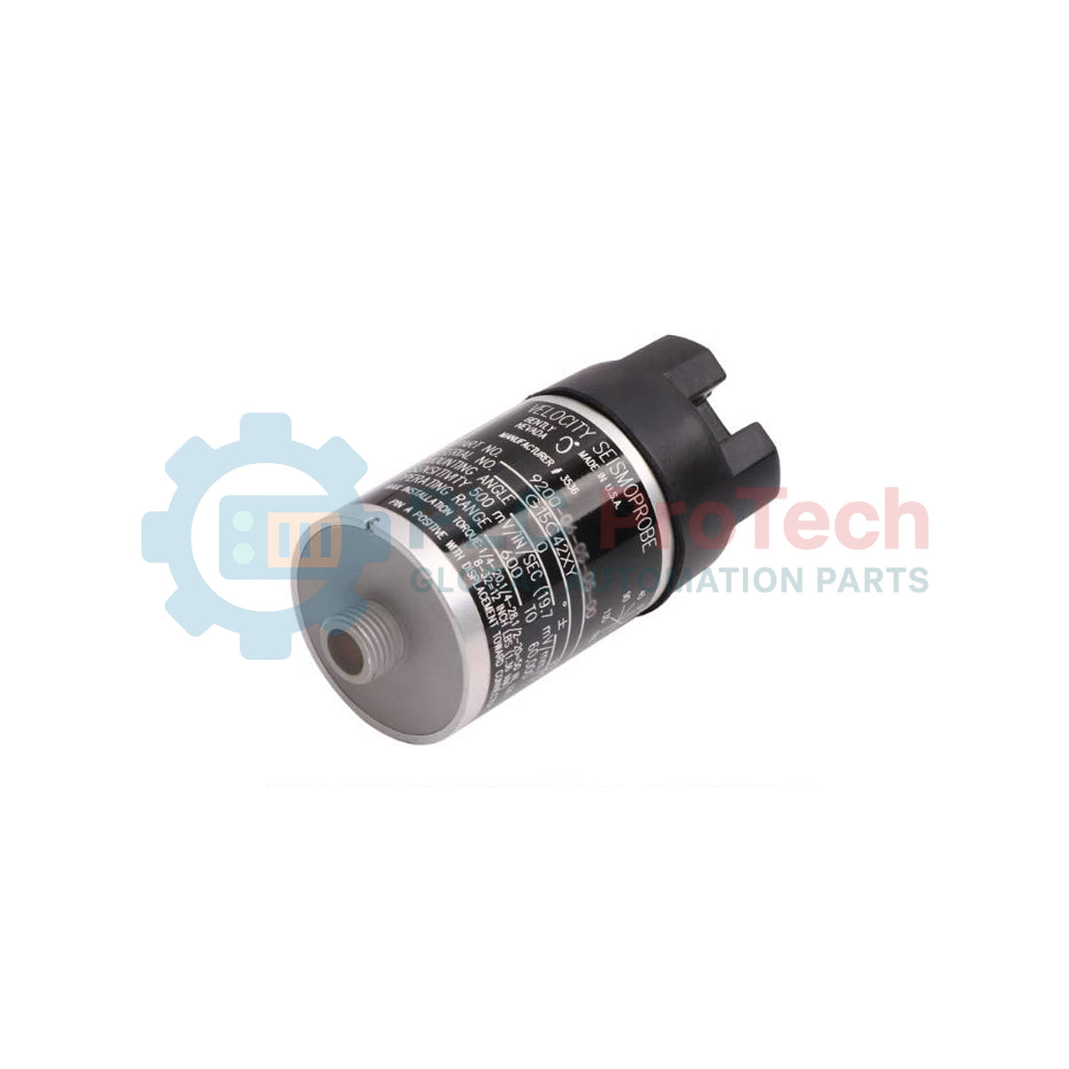
Description
Designed for continuous machinery vibration monitoring, the Bently Nevada 9200-03-05-10-00 functions as a self-generating, two-wire velocity sensor that translates casing vibration into an electrical signal. This moving-coil transducer is engineered specifically for vertical installation configurations, operating at a 90-degree angle to provide high-precision measurements of absolute structural vibration on bearing housings, casings, or structural supports. By utilizing a passive design, this transducer operates without external power, converting physical motion directly into an AC voltage output proportional to vibration velocity.
Features
-
Self-Generating Operation: Moving-coil configuration requires zero external excitation voltage or auxiliary power.
-
Vertical Orientation Calibration: Factory-calibrated for 90 degrees (plus/minus 2.5 degrees) mounting angles.
-
Low-Frequency Capability: Minimum operating frequency rating of 4.5 Hz (270 cpm) for capturing low-speed machinery defects.
-
Terminal Block Interface: Top-mounted terminal block connection eliminates molded cable dependencies for field-terminated wiring.
-
Robust Mounting Interface: Features a circular base equipped with an M10x1 stud for high-frequency transmission.
Applications
- Vertical industrial pumps and motor casing vibration monitoring
- Large fans, blowers, and air-handling equipment maintenance paths
- Hydroelectric generator bearing housing structural tracking
- Casing vibration measurements on steam and gas turbines
Technical Specifications
| Parameter |
Specification Value |
| Manufacturer |
Bently Nevada |
| Model Number |
9200-03-05-10-00 |
| Transducer Type |
Two-wire moving-coil velocity transducer |
| Mounting Angle Option |
90 degrees plus/minus 2.5 degrees (Vertical) |
| Minimum Operating Frequency |
4.5 Hz (270 cpm) |
| Connection Option |
Terminal block, top mount (no cable included) |
| Mounting Base |
Circular base with M10x1 threaded stud |
| Agency Approvals |
Option 00 (No hazardous area approvals) |
| Shipping Weight (Calculated) |
2.0 kg |
Connections and Interfaces
The top-mounted terminal block option simplifies on-site wiring without requiring proprietary molded connector cables. Ensure proper polarity connections to preserve signal phase relative to machinery vibration direction.
| Terminal designation |
Signal Assignment |
| A (+) |
Signal Positive (High side of coil) |
| B (-) |
Signal Negative (Low side of coil / Common) |
| Shield / Case Ground |
Cable shield termination (to be isolated at the sensor case and grounded at the monitor end only) |
Empirical Engineering Insights
Alternative Models & Compatibility
The 9200 series moving-coil Seismoprobe is a legacy mechanical design. It is highly valued because it does not require external power loops, unlike modern solid-state piezo-velocity sensors (such as the Bently Nevada 330500 Velomitor). If you are replacing a 9200 unit, you must match the mounting angle option exactly. A vertical "-03" model (90 degrees) cannot be replaced with a horizontal "-01" or "-02" model, as the internal spring suspension is physically tuned to counteract gravity only at the specified operating orientation.
Application Pitfalls & Engineering Notes
Cross-axis sensitivity is a known limitation of moving-coil transducers. To prevent physical wear on the internal coil guide and to avoid false signal generation, the sensor must not deviate more than plus/minus 2.5 degrees from the vertical axis. Additionally, check for nearby magnetic fields; because the 9200 uses an internal permanent magnet and moving coil, high-power magnetic fields from adjacent large motors can induce noise directly into the signal path.
Commissioning & Wiring Tips
When wiring to the terminal block, prevent dynamic stress on the terminals by installing a physical strain relief clamp within 100 mm of the sensor head. This prevents wiring fatigue from continuous structural vibration. Always use twisted, shielded cable (typically 18 AWG to 22 AWG) and ensure the shield is floated at the sensor and grounded at the rack monitor to mitigate ground loop noise.
Installation Guidelines
CRITICAL WARNING: Prior to installation or replacement, ensure that all machinery is safely locked out and de-energized. Do not mount the transducer on surfaces that exceed the maximum rated thermal capacity of the unit, as overheating can permanently demagnetize the internal moving-coil system, causing permanent sensitivity loss.
1
Prepare the mounting surface. It must be flat, smooth, and free of paint, rust, or debris. A surface finish of 1.6 micrometers (63 microinches) or better is recommended.
2
Apply an approved thread-locking compound to the M10x1 stud threads. Thread the sensor onto the mounting hole and torque to the manufacturer's specification using a flat wrench on the housing hex flats (do not hand-tighten by twisting the terminal head).
3
Confirm vertical alignment using a precision level or inclinometer. The deviation from vertical must be less than 2.5 degrees.
4
Connect the field wiring to the terminal block. Secure the cable with local flexible conduit or strain-relief clamps to prevent mechanical fatigue on the connections.