Description
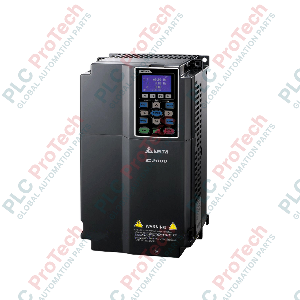
Executing precise motor control across heavy-duty industrial environments, the Delta Electronics VFD750C43A-21 operates as a high-capacity C2000 Series variable frequency drive. Engineered to support both permanent magnet and induction motors, this module provides highly reliable speed, torque, and position control. Its dual-rating architecture allows seamless optimization for normal duty (variable torque) or heavy duty (constant torque) loads, ensuring system versatility. Built-in PLC functionality paired with robust network interface options simplifies complex automated topologies by localizing control functions directly within the drive chassis.
Features
-
Dual-Rating Performance: Configurable for Normal Duty (ND) or Heavy Duty (HD) output profiles to match diverse load types.
-
High-Performance Control: Supports FOC (Field Oriented Control), sensorless vector control, and closed-loop control methods.
-
Integrated PLC: Features a built-in 10k-step PLC capacity to run local logic programs and reduce master controller overhead.
-
Modular Hardware Architecture: Hot-swappable keypad, removable terminal blocks, and extensible I/O slot configurations.
-
Advanced Thermal Design: Heat sink separation design isolates electronic components from air-duct dust contamination.
Applications
-
Heavy-Duty Extruders and Mixers: Provides high starting torque and precise speed regulation under varying viscosity loads.
-
Municipal Water & Wastewater Pumps: Manages variable torque flow demands efficiently with built-in PID control loops.
-
Material Handling Systems: Coordinates smooth acceleration/deceleration ramps on heavy-load conveyors and crane hoist axes.
-
Industrial Compressor Stations: Delivers stable pressure control while maximizing system electrical efficiency.
Technical Specifications
| Parameter |
Specification Value |
| Manufacturer |
Delta Electronics |
| Model / SKU |
VFD750C43A-21 |
| Series |
C2000 Series |
| Operating Voltage Range |
323 to 528 VAC (3-Phase) |
| Rated Output Capacity (kVA) |
Normal: 120 kVA / Heavy: 114 kVA |
| Rated Output Current (A) |
Normal: 150 A / Heavy: 143 A |
| Applicable Motor Output (kW) |
Normal: 75 kW / Heavy: 55 kW |
| Applicable Motor Output (HP) |
Normal: 100 HP / Heavy: 75 HP |
| Input Current (A) |
Normal: 157 A / Heavy: 149 A |
| Frequency Tolerance |
47 to 63 Hz |
| Efficiency |
97.8% |
| Frame Size |
Frame D |
| Dimensions (L x W x H) |
33.0 cm x 27.5 cm x 55.0 cm |
| Net Weight |
38.5 kg |
| Shipping Weight |
41.0 kg |
Empirical Engineering Insights
Alternative Models & Compatibility
When replacing older Delta VFD-B or VFD-F series units, note that the physical footprint of Frame D in the C2000 series differs. Re-drilling of mounting plates is typically required. Parameter migration can be streamlined using Delta’s VFDSoft software, but motor tuning parameters must be re-run on-site (especially if operating in FOC vector modes) due to improvements in the auto-tuning algorithms of this firmware revision.
Application Pitfalls & Engineering Notes
Operating the VFD750C43A-21 at high altitudes (above 1000 meters) or in ambient temperatures exceeding 40 degC requires a derating of 1% output current per additional 100 meters or per additional Celsius degree. Additionally, when using a braking resistor for high-inertia deceleration loads, ensure that the braking parameter settings correspond precisely to the external resistor thermal limits to prevent overvoltage tripping (OV fault code).
Commissioning & Wiring Tips
Control terminals utilize pluggable spring-clamp blocks. To prevent electromagnetic interference (EMI) on the 4-20mA analog speed reference lines, ensure that control cables are run in separate dedicated metal conduits from the primary three-phase output motor cables. Connect the cable shield exclusively to the grounding terminal at the drive chassis end to eliminate ground loop current induction.
Installation Guidelines
CRITICAL WARNING:
Hazard of Electrical Shock. Ensure all main input power sources are disconnected and locked out. Wait a minimum of 10 minutes after physical power disconnection for the internal DC bus capacitors to completely discharge before removing the terminal housing cover or touching any internal electrical connections.
1
Mounting: Mount the Frame D enclosure vertically on a flat, non-flammable vertical backplane. Ensure a minimum clearance of 150mm above and below the cooling vents to facilitate unrestricted airflow.
2
Power Connection: Connect the three-phase input power lines to terminals R/L1, S/L2, and T/L3. Connect the motor supply leads to terminals U/T1, V/T2, and W/T3. Do not connect input power to the output terminals as this will destroy the IGBT power modules.
3
Grounding: Connect the main protective earth (PE) terminal to the industrial plant ground grid using low-impedance cables sized in compliance with local electrical safety codes.