Description
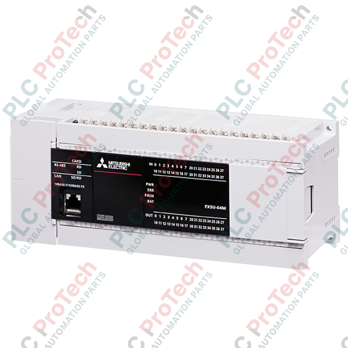
Integrating high-performance control and built-in industrial connectivity, the Mitsubishi Electric FX5U-64MT/ESS serves as a cornerstone processing unit within the MELSEC iQ-F compact PLC range. This controller delivers high-speed processing and robust capacity designed to handle complex automation sequences. Equipped with 32 digital inputs (24 V DC, sink/source) and 32 digital outputs (transistor, source), it provides an exceptional physical I/O density within a compact footprint. Users benefit from embedded Ethernet, RS-485 serial communication, and integrated analog I/O, minimizing the necessity for auxiliary expansion modules in mid-scale industrial systems.
Features
-
High-Speed Execution: Processing speeds of 34 ns for basic instructions ensure responsive system execution.
-
Embedded Ethernet Port: Supports CC-Link IE Field Basic, Modbus/TCP, and direct socket communications.
-
Built-In RS-485 Port: Allows seamless connection to up to 16 Mitsubishi inverters or Modbus/RTU devices.
-
Integrated Analog I/O: Built-in 2-channel analog input (0 to 10 V DC) and 1-channel analog output (0 to 10 V DC).
-
Hardware-Based Positioning: Features 4-axis pulse output (up to 200 kpps) for precise motion control applications.
-
SD Card Slot: Supports standard SD/SDHC cards for program backup, data logging, and easy firmware updates.
Applications
- Multi-axis pick-and-place systems and packaging machinery.
- Pumping station control, water filtration systems, and environmental chambers.
- Automated material handling, conveying networks, and sorting systems.
- Distributed HVAC control and facility monitoring systems.
Technical Specifications Table
| Parameter |
Value / Specification |
| Manufacturer |
Mitsubishi Electric |
| Model Number |
FX5U-64MT/ESS |
| Product Series |
MELSEC iQ-F Series (FX5U) |
| Input Points |
32 Points |
| Input Type |
24 V DC (Sink / Source) |
| Output Points |
32 Points |
| Output Type |
Transistor (Source) |
| Supply Voltage |
100 to 240 V AC (+10% / -15%), 50/60 Hz |
| Power Consumption |
45 W |
| Program Memory |
64k Steps (Flash Memory) |
| Built-in Communication |
Ethernet (1 Port), RS-485 (1 Port) |
| Built-in Analog Inputs |
2 Channels (0 to 10 V DC) |
| Built-in Analog Output |
1 Channel (0 to 10 V DC) |
| Operating Temperature |
-20 to 55 degC (non-freezing) |
| Shipping Weight (Calculated) |
1.00 kg |
| Package Dimensions (Calculated) |
150 mm x 110 mm x 95 mm |
Connections and Interfaces
| Terminal Block Section |
Signal Assignment / Function |
| Power Terminals |
L (Line), N (Neutral), Protective Earth (Ground) |
| Digital Inputs (X0 - X37) |
S/S Terminal determines Sink or Source configuration. 24 V DC excitation. |
| Digital Outputs (Y0 - Y37) |
+V (External Power Supply Input), COM (Common negative path for source outputs) |
| Built-in Analog Input |
V1+, V2+, V- (Common ground for both channels) |
| Built-in Analog Output |
V+, V- (Voltage output channel) |
Alternative Models & Compatibility
The FX5U-64MT/ESS acts as a modern upgrade path for legacy FX3U-64MT/ESS installations. While mounting footprints and programming software (transitioning from GX Works2 to GX Works3) differ, physical conversion brackets and the GX Works3 translation utility minimize migration effort. Ensure you verify output polarity: the /ESS model features source transistor outputs, unlike the /ES version which features sink transistor outputs.
Application Pitfalls & Engineering Notes
When switching inductive loads such as DC solenoid valves or relays using the transistor outputs, always install an external surge protection diode across the load. Overloading a transistor output terminal past 0.5 A can cause internal hardware damage. Note that the built-in analog inputs/outputs are non-isolated; using external signal isolators is highly recommended if cable runs extend outside the local control cabinet.
Commissioning & Wiring Tips
The built-in RS-485 communication line utilizes a 3-pin spring-clamp terminal. Always enable the terminating resistor (built-in, switch-selectable) at both physical ends of the RS-485 network segment to prevent signal reflections. Ensure that the SG (Signal Ground) line is properly linked across all nodes to stabilize common-mode voltages.
Installation Guidelines
CRITICAL WARNING: Completely isolate and de-energize the main AC power supply feeding the enclosure before performing any mounting, terminal wiring, or maintenance activities. Failure to do so exposes field staff to hazardous voltages and risk of severe shock.
1
Mount the CPU module on a standard 35 mm DIN rail or directly to the cabinet backplate using mounting screws, ensuring proper vertical orientation for optimal heat dissipation.
2
Connect the protective earth terminal directly to the main grounding bar inside the panel using a low-impedance conductor of at least 2.0 mm square.
3
Wire the AC power line (100 to 240 V AC) using recommended ferruled terminals, taking care to isolate signaling cables from high-power distribution lines.