Description
Executing high-precision speed, torque, and position control, the Mitsubishi Electric MR-J3-60A is an AC servo drive engineered for seamless integration within the MELSERVO-J3 system architecture. This amplifier utilizes sine-wave PWM control and closed-loop feedback systems to achieve rapid response times and minimal settling overhead. Designed to drive compatible rotary and linear servo motors up to 600W (0.6 kW), the unit incorporates an analog and pulse train general-purpose interface to interface directly with external PLC motion controllers, positioning modules, and CNC systems. Built-in performance tuning algorithms continuously monitor mechanical resonance, automatically adjusting vibration suppression filters to ensure peak structural stability during high-acceleration duty cycles.
Features
-
Real-Time Auto-Tuning: Automatically computes optimum gain values, adapting to varying mechanical inertia ratios during continuous machine runtimes.
-
Vibration Suppression: Advanced dual-frequency vibration suppression filters mitigate structural oscillation at both the tool-tip and machine base.
-
High-Resolution Feedback Compatibility: Integrates with 18-bit absolute/incremental encoders, delivering high positioning constancy and smooth low-speed performance.
-
Flexible Control Modes: Configurable via parameters to operate in position, speed, or torque control modes via general-purpose analog or pulse train command inputs.
-
Built-In Diagnostic Monitoring: Onboard 5-digit, 7-segment LED display provides direct monitoring of internal status registers, input/output signals, and alarm history codes.
Applications
- High-speed pick-and-place packaging systems.
- Multi-axis Cartesian robotic positioning systems.
- Precision semiconductor handling and cleanroom manufacturing machinery.
- Automated tool-feed mechanisms in metalworking and CNC auxiliary axes.
- Electronic assembly and printing press alignment rollers.
Technical Specifications
| Parameter |
Value / Specification |
| Manufacturer |
Mitsubishi Electric |
| Model / SKU |
MR-J3-60A |
| Series |
MELSERVO-J3 (General-Purpose Interface Type A) |
| Rated Output Capacity |
0.6 kW (600W) |
| Rated Output Current |
3.2 A |
| Rated Output Voltage |
3-phase 170 V AC |
| Input Power Supply |
3-phase or 1-phase 200 to 230 V AC, 50/60 Hz |
| Permissible Voltage Fluctuation |
170 to 253 V AC |
| Control System |
Sine-wave PWM control, current control system |
| Dynamic Brake |
Built-in |
| Safety Features |
Overcurrent shutdown, regenerative overvoltage shutdown, overload shutoff (thermal), encoder error protection |
| Ambient Operating Temperature |
0 to 55 degC (non-freezing) |
| Ambient Operating Humidity |
Up to 90% RH (non-condensing) |
| Physical Dimensions |
168 mm (H) x 40 mm (W) x 135 mm (D) |
| Unit Net Weight |
1.0 kg |
| Shipping Weight (Calculated) |
1.8 kg |
| Package Dimensions (Calculated) |
240 mm x 180 mm x 120 mm |
| Country of Origin |
Japan |
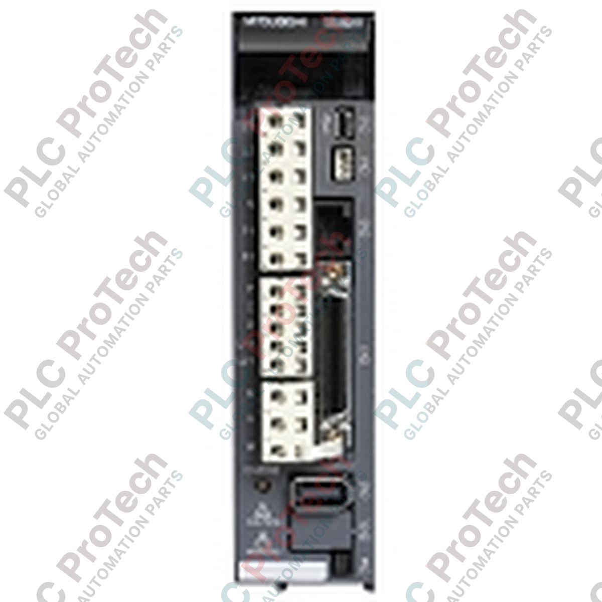
Connections and Interfaces
| Port / Terminal Block |
Functional Assignment / Purpose |
| L1, L2, L3 |
Main circuit 3-phase AC power input terminal connections. |
| L11, L21 |
Control circuit single-phase AC power input terminal connections. |
| U, V, W |
Three-phase power outputs routed directly to servo motor windings. |
| CN1 (50-Pin) |
I/O connector for analog inputs, command pulse inputs, digital inputs/outputs, and encoder output pulses. |
| CN2 (10-Pin) |
High-speed serial encoder communication connection for motor feedback signals. |
| CN3 (Mini-USB) |
PC communications port for interfacing with MR Configurator setup software. |
| P+, C, D |
Terminal pins designated for internal built-in dynamic braking or external regenerative options. |
Empirical Engineering Insights
Alternative Models & Compatibility
When migrating legacy architectures, notice that the MR-J3-60A utilizes a general-purpose digital pulse train and analog interface (A-type). It cannot directly replace an "MR-J3-60B" network variant designed for SSCNET III bus configurations. If replacing this model with newer generations (such as the MR-J4-60A), a conversion adapter unit (such as the MR-J4-T20 transition kit) and parameter mapping software are required because of pin-out differences on the 50-pin CN1 connector.
Application Pitfalls & Engineering Notes
Under continuous high-acceleration cycling, the built-in regenerative capacity of the drive can easily exceed its thermal dissipation rating, yielding an AL.30 (Regenerative Error) trip. If active braking cycles are frequent, an external regenerative resistor option (e.g., MR-RB12) must be integrated and parameterized. Additionally, inside poorly ventilated electrical enclosures, make sure clear airflow margins are maintained: 40 mm minimum clear space above/below the drive frame to prevent premature thermal degradation of the internal capacitor banks.
Commissioning & Wiring Tips
To protect command inputs from electrical noise-induced positioning drift, differential line driver inputs on CN1 (OPG/OPC inputs) should always be selected rather than open-collector wiring paths. Ensure the encoder shield drain wire is clamped securely to the metal shell of the CN2 connector to minimize ground loop loops. If the drive trips with an AL.16 (Encoder Communication Error) immediately on startup, check the integrity of the ground bond between the motor housing and the electrical sub-panel.
Installation Guidelines
CRITICAL WARNING
Disconnect all incoming AC power lines prior to installation or disassembly. Wait at least 15 minutes after power-off to allow internal high-voltage capacitors to discharge completely. Verify the voltage between terminals (P+) and (N-) is under 20 V DC with a calibrated voltmeter before touching any terminal connections or wiring structures. Failure to do so may result in severe electric shock or hardware destruction.
1
Mount the drive vertically inside a clean, IP54-rated metal enclosure. Ensure there is adequate mechanical separation from adjacent high-heat equipment such as line reactors or breaking resistors.
2
Connect the physical system ground to the protective earth terminal (PE) before installing control or main line inputs to prevent ESD damage.
3
Verify that the phase relationships of output connections U, V, and W exactly match the corresponding terminals of the servo motor. Do not swap phases to reverse direction, as this will lead to an immediate motor runaway fault.
4
Check that any control circuit jumpers between P+ and D are securely connected unless an external regenerative option is actively configured in the drive parameters.