Description
Designed for high-precision temperature acquisition in demanding industrial environments, the Mitsubishi Electric Q68TD-G-H02 is a channel-to-channel isolated thermocouple input module for the MELSEC Q series PLC platform. This module supports up to 8 independent input channels, delivering robust protection against ground loops and common-mode electrical noise through dedicated transformer isolation. Built to handle standard sensor variations, it integrates native cold junction compensation (CJC) and precise analog-to-digital signal conversion parameters, making it an ideal choice for multi-zone furnace control, chemical processing, and plastic extrusion applications.
Key Features
-
High-Channel Isolation: Channel-to-channel and channel-to-CPU transformer isolation prevents cross-talk and ensures system stability under challenging electrical conditions.
-
Sensor Disconnection Detection: Independent diagnostic tracking triggers warning flags immediately when a sensor wire break is detected on any specific channel.
-
Broad Thermocouple Support: Compliant with international standards including JIS C1602-1995, IEC 60584-1, and IEC 60584-2.
-
Fast Update Cycle: Sampling and conversion complete within 640 ms across all 8 active channels.
-
Dynamic Temperature Scaling: Outputs 16-bit signed binary values representing physical measurement ranges from -2700 to 18200.
Applications
- Multi-zone thermal processing ovens and industrial manufacturing furnaces.
- Petrochemical and chemical reactor vessel thermal monitoring.
- Plastic extrusion machines and injection molding hot-runner systems.
- Power generation plant steam and bearing temperature diagnostics.
Technical Specifications
| Parameter |
Specification Value |
| Manufacturer |
Mitsubishi Electric |
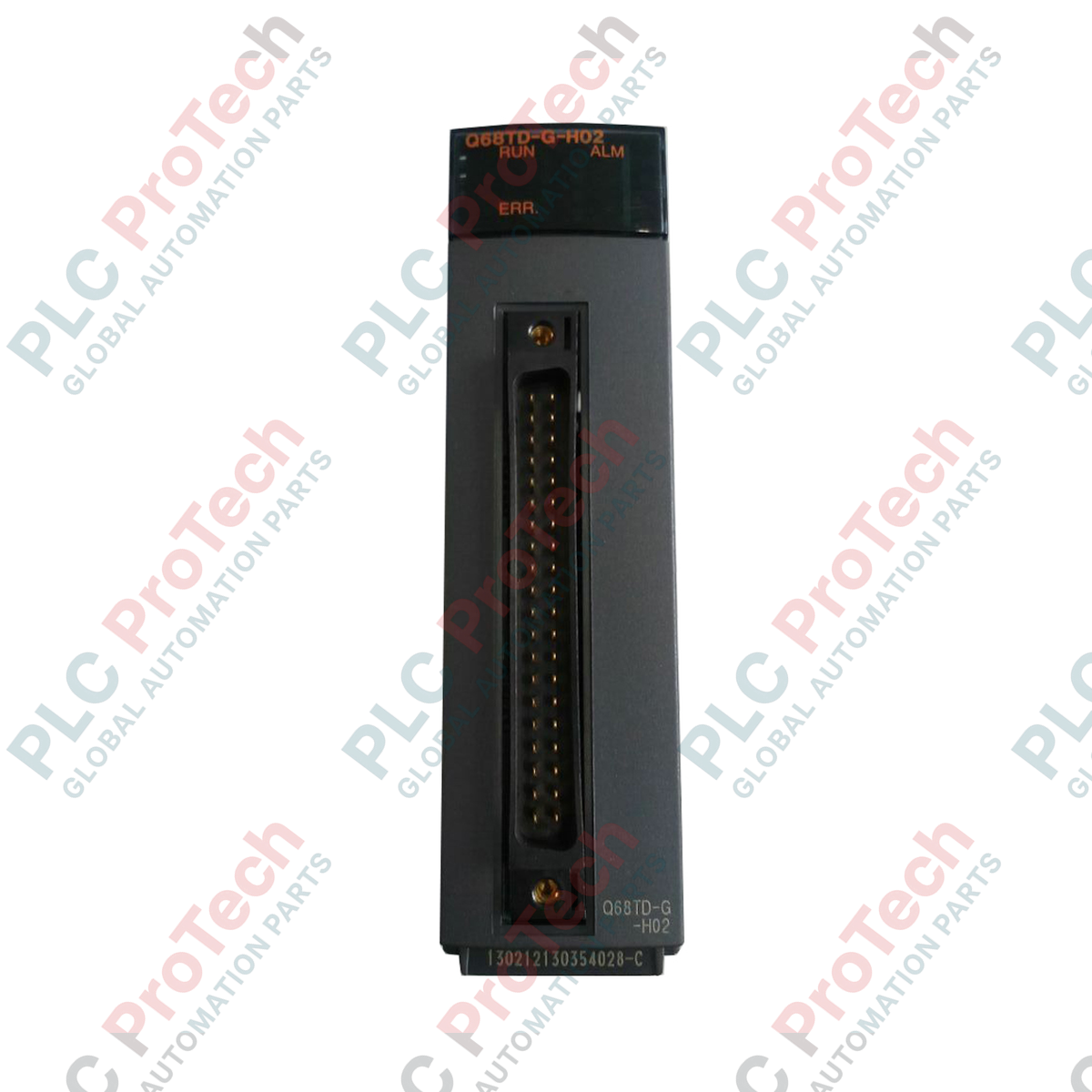
| Model Number |
Q68TD-G-H02 |
| Module Type |
Channel-to-channel insulation thermocouple input unit |
| Input Channels |
8 channels (plus cold junction compensation channel) |
| Digital Output Format |
16-bit signed binary (-2700 to 18200) |
| Thermocouple Standards |
JIS C1602-1995, IEC 60584-1 (1995), IEC 60584-2 (1982) |
| Resolution (B, R, S, N) |
0.3 degC |
| Resolution (K, E, J, T) |
0.1 degC |
| Sampling Cycle |
320 ms / 8 channels |
| Conversion Speed |
640 ms / 8 channels |
| Channel-to-Channel Insulation |
Transformer insulation (1000 Vrms AC for 1 minute) |
| Channel-to-CPU Insulation |
Transformer insulation (500 Vrms AC for 1 minute) |
| Insulation Resistance |
10 MOhm or more at 500 VDC |
| Internal Current (5 VDC) |
0.65 A |
| I/O Points Occupied |
16 points (Intelligent function module) |
| External Interface |
40-pin connector (Requires A6CON1, A6CON2, or A6CON4) |
| Module Dimensions |
13 cm x 2.74 cm x 10.2 cm |
| Net Weight |
0.22 kg |
| Shipping Weight |
1.2 kg |
Empirical Engineering Insights
Alternative Models & Compatibility
When migrating older Q-Series setups that utilize non-insulated modules (such as the standard Q64TD), the I/O assignment profiles must be revised in GX Works2 or GX Works3. Since the Q68TD-G-H02 utilizes a 40-pin connector interface rather than a screw-terminal block, direct drop-in replacement is not physically possible without rewiring or employing an external terminal conversion unit.
Application Pitfalls & Engineering Notes
While the module provides 1000 Vrms AC insulation between input channels, the cold junction compensation (CJC) sensor tracking circuit is non-isolated from the sequencer's internal power supply line. Ensure that temperature sensor shields are grounded correctly and keep them isolated from external power cabling to prevent capacitive coupling and potential drift in high-voltage industrial panels.
Commissioning & Wiring Tips
To avoid generating misleading channel-disconnection diagnostic codes, unused thermocouple input channels must be explicitly disabled in the intelligent function module parameter settings. If a channel remains enabled in the system configuration without a connected thermocouple, the module will permanently flag an open-loop system fault.
Installation Guidelines
CRITICAL WARNING: Prior to mounting or removing this module, isolate and switch off all external power supplies connected to the PLC rack and output loads. Failure to fully de-energize the assembly can cause unexpected diagnostic faults, internal component degradation, or hardware failure.
1
Power down the MELSEC Q base unit completely before inserting the module into the designated slot.
2
Hook the bottom tab of the module into the base unit's guide slot, then push the module firmly into place until the top latch clicks.
3
Secure the module lock screw (M3 size) to a torque of 0.36 to 0.48 N-m to guarantee continuous grounding contact.
4
Wired connections should be terminated using the compatible 40-pin connector (A6CON1/A6CON2/A6CON4). Shielded thermocouple extension wire must be routed separately from high-voltage AC lines.