Description
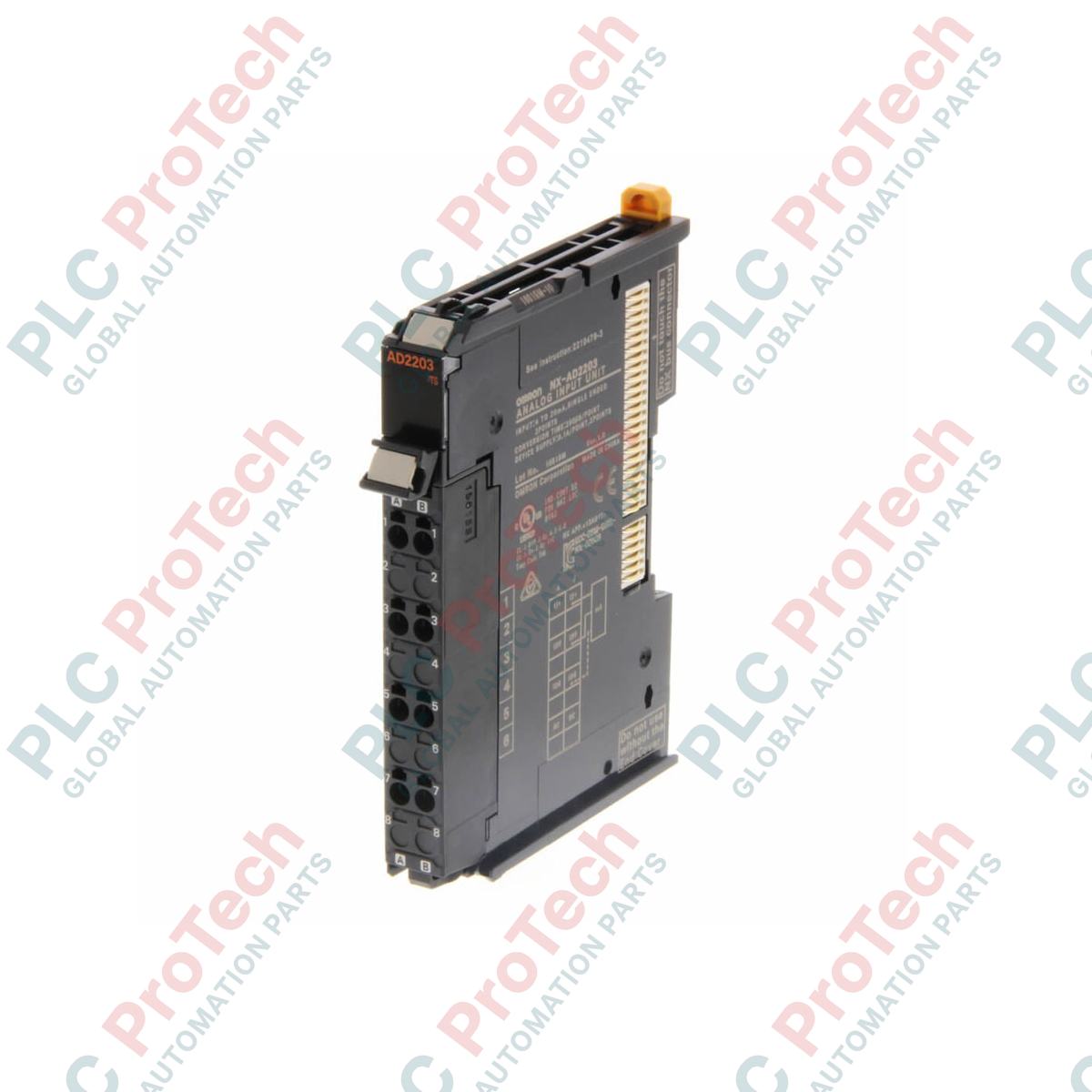
Integrating seamlessly into the Sysmac automation architecture, the Omron NX-AD2203 Analog Input Unit provides precise, high-density current signal acquisition for distributed industrial control systems. This ultra-compact slice I/O module features two analog inputs calibrated for standard 4 to 20 mA current loops, allowing direct interfacing with process transmitters, flow meters, and pressure sensors. Operating directly on the synchronous NX bus, it enables high-speed data acquisition synchronized with the machine control cycle, reducing signal jitter and enhancing overall loop stability in demanding applications.
Key Features
-
Dual-Channel Current Input: Two independent single-ended inputs configured specifically for 4 to 20 mA signals.
-
High-Density 12mm Width: Slimline profile reduces required DIN-rail footprint inside electrical control enclosures.
-
Push-In Plus Technology: Fast, screwless clamping terminal block ensures gas-tight, vibration-proof wiring connections.
-
Synchronous I/O Refreshing: Synchronizes analog-to-digital conversions directly with the EtherCAT master controller scan cycle.
-
Bus-Powered Efficiency: Internal circuitry draws power directly from the NX bus, eliminating the need for dedicated external logic power lines.
Applications
- Process control loops monitoring liquid flow, gas pressure, and vessel temperature.
- Water and wastewater monitoring stations integrating remote loop-powered field transmitters.
- Chemical dosing and mixing machinery requiring highly synchronized analog feedback.
- HVAC and environmental control systems tracking relative humidity and differential pressure.
Technical Specifications
| Parameter |
Specification |
| Manufacturer |
Omron |
| Model Code |
NX-AD2203 |
| Input Type |
Analog Current (4 to 20 mA) |
| Number of Inputs |
2 single-ended channels |
| Resolution |
1/8000 |
| Conversion Time |
250 microseconds per channel |
| Input Impedance |
Approx. 250 ohms |
| Power Supply Method |
Supply from the NX bus |
| I/O Current Consumption |
No consumption from the I/O power supply terminals |
| External Terminals |
Screwless clamping terminal block (8 terminals) |
| Dimensions (W x H x D) |
12 mm x 100 mm x 71 mm |
| Net Weight |
0.070 kg (70 grams) |
| Shipping Weight (Calculated) |
0.150 kg |
Connections and Interfaces
The front-facing terminal block utilizes a spring-loaded clamp layout designed to expedite physical wiring and ensure maintenance-free operations under high mechanical vibration.
| Terminal No. |
Signal Name |
Function / Connection Details |
| A1 |
AMP1+ |
Analog input positive terminal for Channel 1 |
| A3 |
AMP2+ |
Analog input positive terminal for Channel 2 |
| A5 |
COM1 |
Analog common terminal for Channel 1 |
| A7 |
COM2 |
Analog common terminal for Channel 2 |
| B1 / B3 |
NC |
No connection (internal separation) |
| B5 / B7 |
SHIELD |
Functional ground terminals for cable shield termination |
Empirical Engineering Insights
Alternative Models & Compatibility
The NX-AD2203 is designed specifically for standard 4 to 20 mA current loops. If your field sensors output 0 to 20 mA or raw voltage signals (such as 0 to 10 VDC), you must use the alternative NX-AD2603 or the voltage-specific NX-AD2204. Ensure your Sysmac Studio software is updated to version 1.10 or higher to register and configure this module on the EtherCAT Coupler network without firmware errors.
Application Pitfalls & Engineering Notes
Because this module draws its primary operational logic power directly from the internal NX bus, its reported I/O current consumption is 0.00 A. However, this means the loop power for your 2-wire field transmitters must be supplied by an external 24 VDC auxiliary power distribution block. Do not attempt to draw transmitter loop power directly from the NX-AD2203 terminals, as it lacks internal transmitter power distribution.
Commissioning & Wiring Tips
To ensure the 1/8000 resolution measurement remains noise-free in high-EMI environments (such as proximity to active VFDs), always run shielded twisted-pair (STP) cabling for the analog input lines. Ground the cable shields directly to the B5 or B7 shield terminals of the module. For solid wire or ferruled wire connections, insert directly into the Push-In Plus terminal without tools; to release, use a small flat-blade screwdriver on the orange release button.
Installation Guidelines
CRITICAL WARNING: PHYSICAL SAFETY PROTOCOL
Ensure the entire PLC system, EtherCAT coupler, and associated field device power supplies are completely de-energized before mounting, removing, or wiring the module. Failure to cut primary power to the NX-bus segment can cause hot-plugging damage to the internal ASIC chips and interrupt active network communications.
1
Align the top and bottom guide rails of the NX-AD2203 slice with the adjacent NX module or coupler on the DIN-rail.
2
Slide the module firmly toward the left until the internal bus connectors click and lock securely into place.
3
Strip field signal wires to 8-10 mm. Fully insert ferrules or solid conductors into the Push-In Plus terminals; pull gently to verify a secure physical connection.