


مشغلات كهربائية مصممة لاستبدال السوائل: درس عملي
This article explains how integrated electric actuators, such as SMC’s e-Actuator series, are transforming industrial motion control by replacing traditional pneumatic and hydraulic systems. It...

الشركة المصنعة: General Electric
Country of origin:الولايات المتحدة
نوع المنتج: لوحة توزيع الطاقة
الدفع: تحويل بنكي، ويسترن يونيون
الوزن: 2500ج
Dimensions: 17.78(W) × 7.62(D) × 51.81(H) cm
ميناء الشحن: شيامن
الضمان: 12 شهرًا
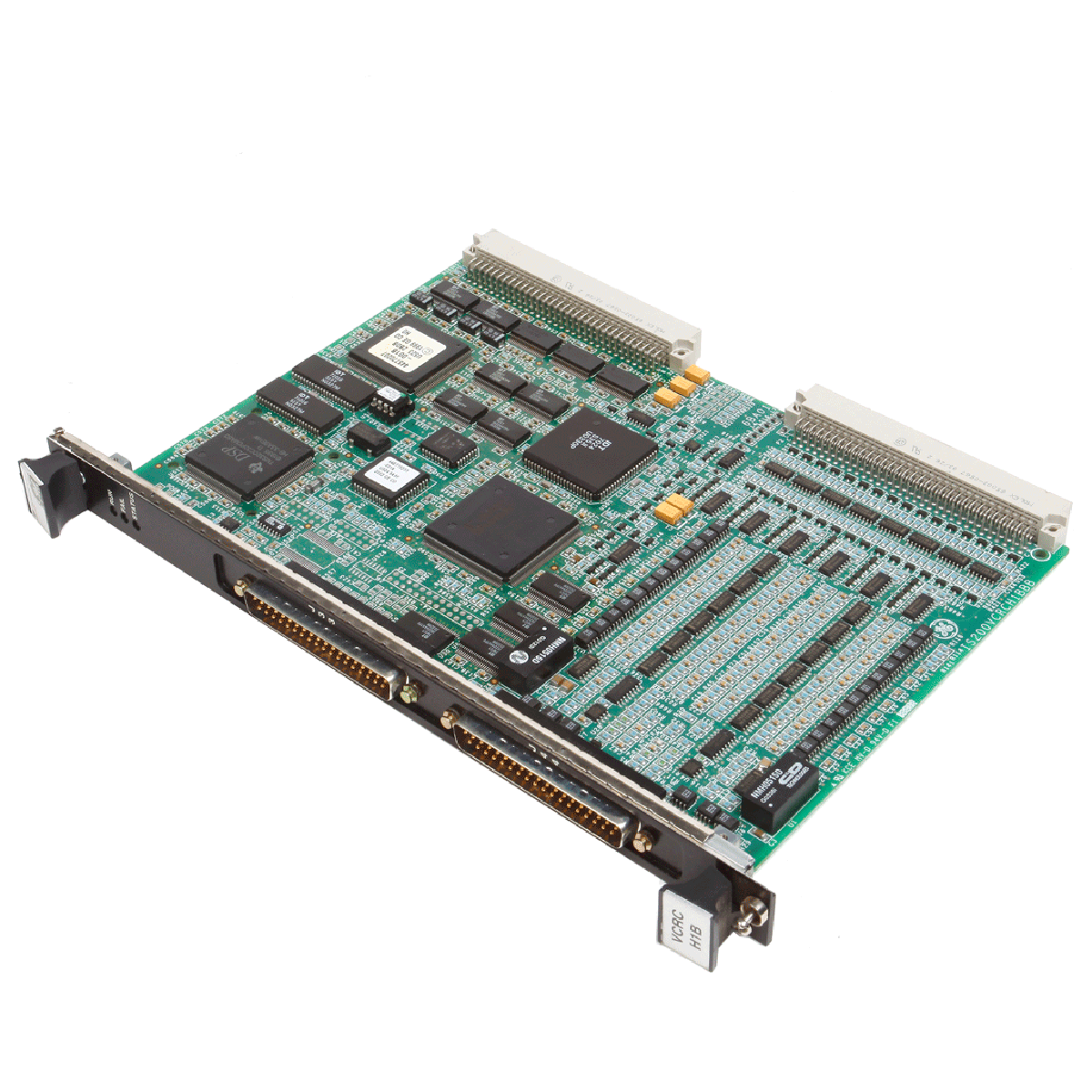
The IS200JPDCG1A functions as a component-dense power distribution board within the General Electric Mark VI Turbine Control System. It combines input and output distribution functions to deliver 125 V dc, 115/230 V ac, and 28 V dc to other terminal boards and packs within steam, gas, or wind turbine management setups. The IS200JPDCG1A acts as the primary hosting module for a Power Distribution System Feedback (PPDA) I/O pack, directly capturing and multiplexing diagnostic feedback signals from both local circuits and daisy-chained upstream distribution boards to facilitate system monitoring via the IONet.
| Module Version | Configuration Detail |
|---|---|
| IS2020JPDCG01 | Standard version for most power distribution applications |
| IS2020JPDCG02 | Special version including a wire jumper on the D1 diode assembly to enable JD2 Battery B input as an output |
| Item | Description / Value |
|---|---|
| Manufacturer | General Electric |
| Series | Mark VI Speedtronic |
| Part Number | IS200JPDCG1A |
| Functional Abbreviation | JPDC |
| 28 V dc Inputs (JR, JS, JT) | 19 A max each, 15 V max |
| 28 V dc Un-fused Outputs (J1, JP1, JCR, JCS, JCT, JRS, JSS, JTS) | 13 A max per pin; total current not to exceed 12.5 A |
| 28 V dc Fused Outputs (JR1-JR10, JS1-JS8, JT1-JT8) | 1.6 A polyfuse per connection |
| 115/230 V ac Input (JAC) | 13 A max, 115/230 V ac, 50/60 Hz (30 A circuit breaker protection) |
| 115/230 V ac Outputs (JAC1, JAC2) | 10 A max each, protected by 10 A 250 V time-delay fuses |
| 125 V dc Battery Inputs (JD1, JD2) | 20 A max total current, 90-145 V dc input voltage range |
| 125 V dc DACA Input (JZ2) | 10 A max, 125 V dc nominal, 145 V dc maximum |
| Impedance to Ground | >75 kOhm (JP1 jumper in place), >1500 kOhm (JP1 jumper removed) |
| Operating Temperature Range | -30 to 65 degC (-22 to 149 Fahrenheit) |
| Board Size | 17.2 cm Wide x 48.26 cm High (6.75 in x 19.0 in) |
| Module Size | 17.78 cm Wide x 51.81 cm High x 7.62 cm Deep (7.0 in x 20.4 in x 3 in) |
| Factory Location | Salem, Virginia, USA |
| Connector / Signal | Function |
|---|---|
| JR, JS, JT | 28 V dc Power Supply Inputs |
| JAC | 115/230 V ac Power Input |
| JAC1, JAC2 | 115/230 V ac Power Outputs (JAC1 is switched via SWAC1) |
| JD1, JD2 | 125 V dc Battery Inputs (OR'ed together via diode module D1) |
| JZ2 | 125 V dc DACA Module Connection |
| J1R, J1S, J1T | 125 V dc outputs to external dc/dc 28 V dc power supplies |
| J7A, J7B, J7C | 125 V dc outputs to TRLY Relay Output terminal boards |
| J8A, J8B, J8C | 125 V dc short-circuit limited outputs with 22 Ohm series resistors for TBCI boards |
| P2 | 50-pin ribbon cable connector for diagnostic daisy chain inputs |
| JA1 | 62-pin D-shell connection for the PPDA I/O feedback pack |
| TB1 | 5-screw terminal block for 28 V dc Bus Tie configuration |
| TB2, TB3, TB4 | Direct access terminal blocks for raw analog diagnostic feedback signals |
الشحن السريع العالمي
الإرجاع والضمان
يتم معالجة الطلبات وتسليمها من الاثنين إلى الجمعة (باستثناء العطلات الرسمية).
للاطلاع على الأهلية الكاملة، ورسوم إعادة التخزين، وتفاصيل الإرجاع الدولي، يرجى مراجعة موقعنا الرسمي سياسة الاسترداد والإرجاع .
| Country of origin |
الولايات المتحدة
|

This article explains how integrated electric actuators, such as SMC’s e-Actuator series, are transforming industrial motion control by replacing traditional pneumatic and hydraulic systems. It...

تشرح هذه المقالة كيف تقوم أنظمة PLC بتنفيذ العمليات الرياضية الأساسية مثل الجمع والطرح والضرب والقسمة والباقي والأسس ضمن الأتمتة الصناعية. توضح كيف تقوم هذه الكتل الوظيفية بتحويل إشارات المستشعر...

تشرح المقالة عدة دوال منطقية بوليانية متقدمة تُستخدم في برمجة PLC تتجاوز العمليات الأساسية مثل AND وOR وNOT. وتتناول كيفية استخدام أدوات مثل جداول الحقيقة، والمضاعفات، ومولدات النبضات، ومشغلات شميت...

المنطق البولياني هو أساس كل برنامج PLC. من التحكمات البسيطة في الآلات إلى أنظمة الأتمتة الصناعية المعقدة، تحدد بوابات المنطق كيفية استجابة المتحكمات للتغيرات في المدخلات وظروف التشغيل. يشرح هذا...

تلعب الجدران النارية الصناعية دورًا حيويًا في أمن تكنولوجيا العمليات (OT)، حيث تحمي شبكات PLC وDCS وSCADA من خلال التقسيم، والتحكم في الدخول والخروج، ودمج أنظمة كشف ومنع التسلل (IDS/IPS) بما يتماشى...

تتطور القبضات الروبوتية الحديثة لتتجاوز الفكين الميكانيكيين التقليديين. من أنظمة الالتصاق المستوحاة من حرباء الجيكو والقبضات الناعمة المصنوعة من مواد غذائية إلى الأدوات المدعومة بالذكاء الاصطناعي في...