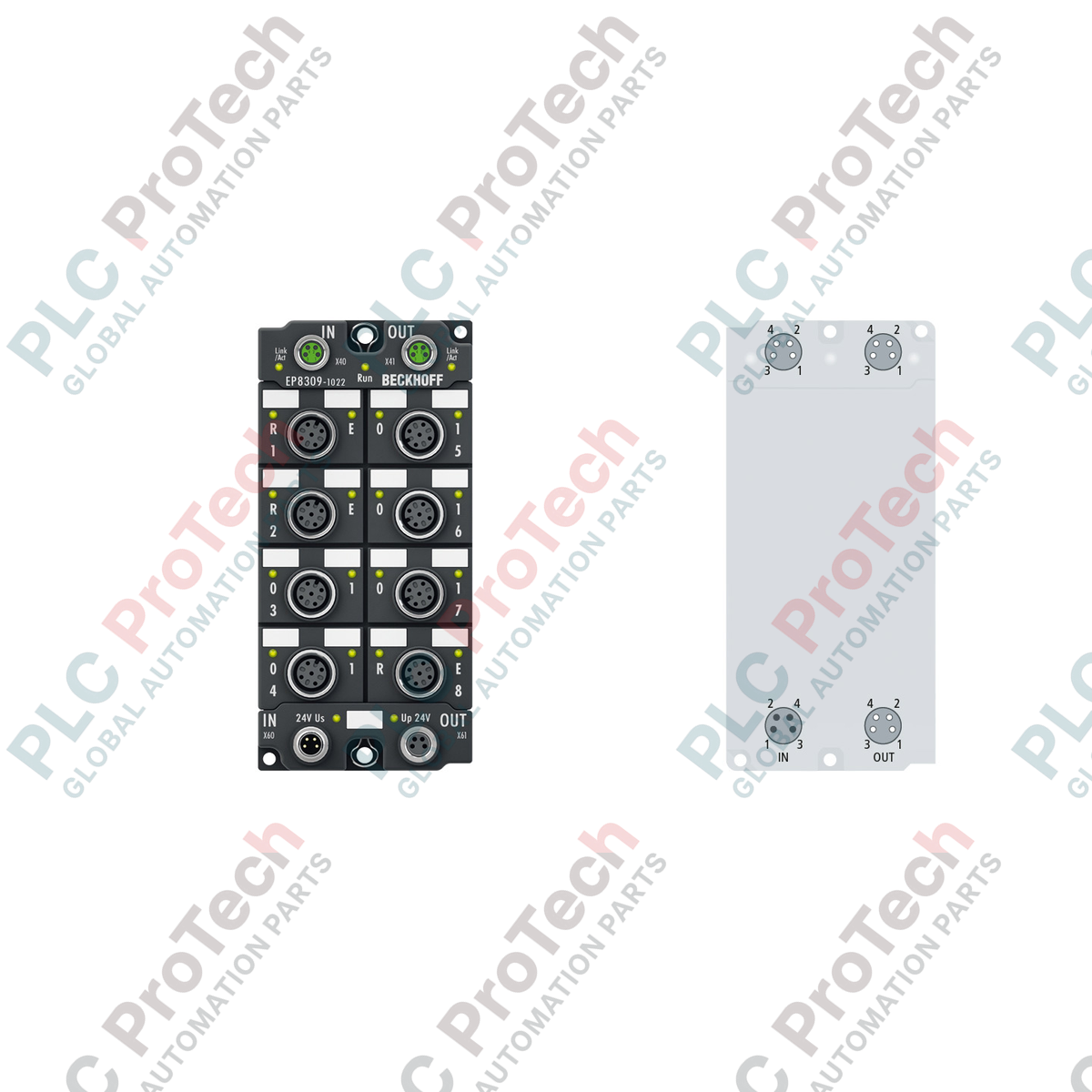
Description
Engineered for decentralized industrial environments requiring diverse signal integration, the Beckhoff EP8309-1022 provides high-density digital, analog, and PWM interfacing directly on the machine layer. This multi-functional EtherCAT Box consolidates multiple I/O types into a single, compact field module, eliminating the need for local control cabinets. Equipped with an integrated EtherCAT interface, it manages bidirectional communication, high-speed digital I/O, precise analog processing, and pulse-width modulation output within severe operating environments. The unit features standard M8 and M12 industrial connections, providing ruggedized IP67 protection and high immunity to electrical noise.
Features
-
Multi-functional I/O Configuration: Integrates digital inputs/outputs, analog inputs, an analog output, and a dedicated PWMi channel in one device.
-
Direct Field Integration: IP65/66/67 rating enables cabinet-free mounting directly on machines, reducing field wiring runs.
-
Configurable Digital Channels: 8 digital ports can be independently parameterized as inputs or outputs.
-
Flexible Analog Interface: Dual 12-bit analog inputs and a single 12-bit analog output supporting standard 0/4 to 20 mA current loops.
-
High-Speed PWMi Output: Single channel supporting up to 1.2 A at frequencies up to 30 kHz for proportional valve control.
-
Robust Electrical Isolation: 500 V isolation barrier protects internal control electronics from external field transients.
Applications
- Decentralized machinery and tool manufacturing lines.
- Proportional valve actuation and hydraulic manifold control.
- Remote sensor and instrument concentration in wet or dusty processing plants.
- Robotic end-of-arm tooling and dynamic assembly cells.
Technical Specifications
| Specification Parameter |
Value / Definition |
| Manufacturer |
Beckhoff |
| Model Number |
EP8309-1022 |
| Protocol / Bus System |
EtherCAT |
| Bus Connection Interface |
2 x M8 socket, shielded, screw type |
| Digital Channels |
8 digital inputs or outputs (channels 6 to 13) |
| Input Filter Time |
3 ms |
| Limit Frequency |
2.5 kHz |
| Analog Inputs |
2 x single-ended, 12-bit, 0/4 to 20 mA (channels 0 and 2) |
| Analog Outputs |
1 x single-ended, 12-bit, 0/4 to 20 mA (channel 15) |
| PWMi Outputs |
1 x 1.2 A, max. 30 kHz (channel 14) |
| Nominal Operating Voltage |
24 V DC (-15% / +20%) |
| Measurement Uncertainty |
Input: < 0.3%, Output: < 0.1% (relative to full scale) |
| Sensor / Actuator Supply |
Sensor from US (control voltage), Actuator from UP (auxiliary voltage) |
| Electrical Isolation |
500 V |
| Protection Rating |
IP65 / IP66 / IP67 (conforms to EN 60529) |
| Operating Temperature |
-25 to +60 degC |
| Storage Temperature |
-40 to +85 degC |
| Housing Material |
PA6 Polyamide |
| Module Dimensions |
60 mm x 126 mm x 26.5 mm |
| Device Weight |
approx. 250 g |
| Shipping Weight |
2.0 kg (packaged) |
Empirical Engineering Insights
Alternative Models & Compatibility
The EP8309-1022 replaces separate, single-purpose IP67 boxes by packing analog, digital, and PWM functionalities into one footprint. It requires a modern TwinCAT configuration profile. Ensure that your TwinCAT 2 (or TwinCAT 3) EtherCAT XML Device Description (ESI) is updated to recognize this multi-functional unit, especially if transitioning from discrete EP1xxx or EP2xxx modules.
Application Pitfalls & Engineering Notes
When executing multi-channel deployment, pay careful attention to the combined current draw on the US (sensor supply) and UP (actuator supply) rails. The internal distribution tracks can overheat or trigger overcurrent faults if the total connected sensor/actuator load exceeds the design limits of the incoming M8 power cables. Additionally, verify signal routing on the PWMi output channel; high-frequency modulation (up to 30 kHz) on unshielded lines can induce noise on adjacent 12-bit analog input channels (0 and 2).
Commissioning & Wiring Tips
For stable current loop operation, ground loop offsets must be mitigated. Since the analog inputs are single-ended, ensure your transmitter sensors share a common potential base with the EP8309-1022's signal ground. For the EtherCAT network connection, use only fully shielded M8 connectors to ensure communication integrity in high-vibration and EMC-heavy environments conforming to EN 61000-6-2 guidelines.
Installation Guidelines
CRITICAL WARNING
Risk of electrical shock and equipment destruction. Isolate and lock out all 24 V DC power sources (both control voltage US and auxiliary voltage UP) before initiating physical installation, cable mating, or terminal modifications. Failure to de-energize may result in severe electronic component damage or operational communication failures on the EtherCAT ring.
1
Mechanical Mounting: Secure the polyamide enclosure to a flat surface using two 3.5 mm holes for M3 screws or two 4.5 mm holes for M4 screws. Ensure the torque does not crack the housing.
2
EtherCAT Port Cabling: Connect incoming and outgoing EtherCAT cables to the M8 sockets. Use shielded connectors and tighten to the recommended torque spec to maintain the IP67 environmental seal.
3
Field Signal Wiring: Connect the digital and analog field devices using standard M12 screw connections. Verify the pin mapping for current loop inputs on channels 0 and 2.
4
Power Supply Initialization: Connect the 24 V DC supply cables. Verify that LEDs light up and indicate solid link status before executing the online physical node discovery in your control software.