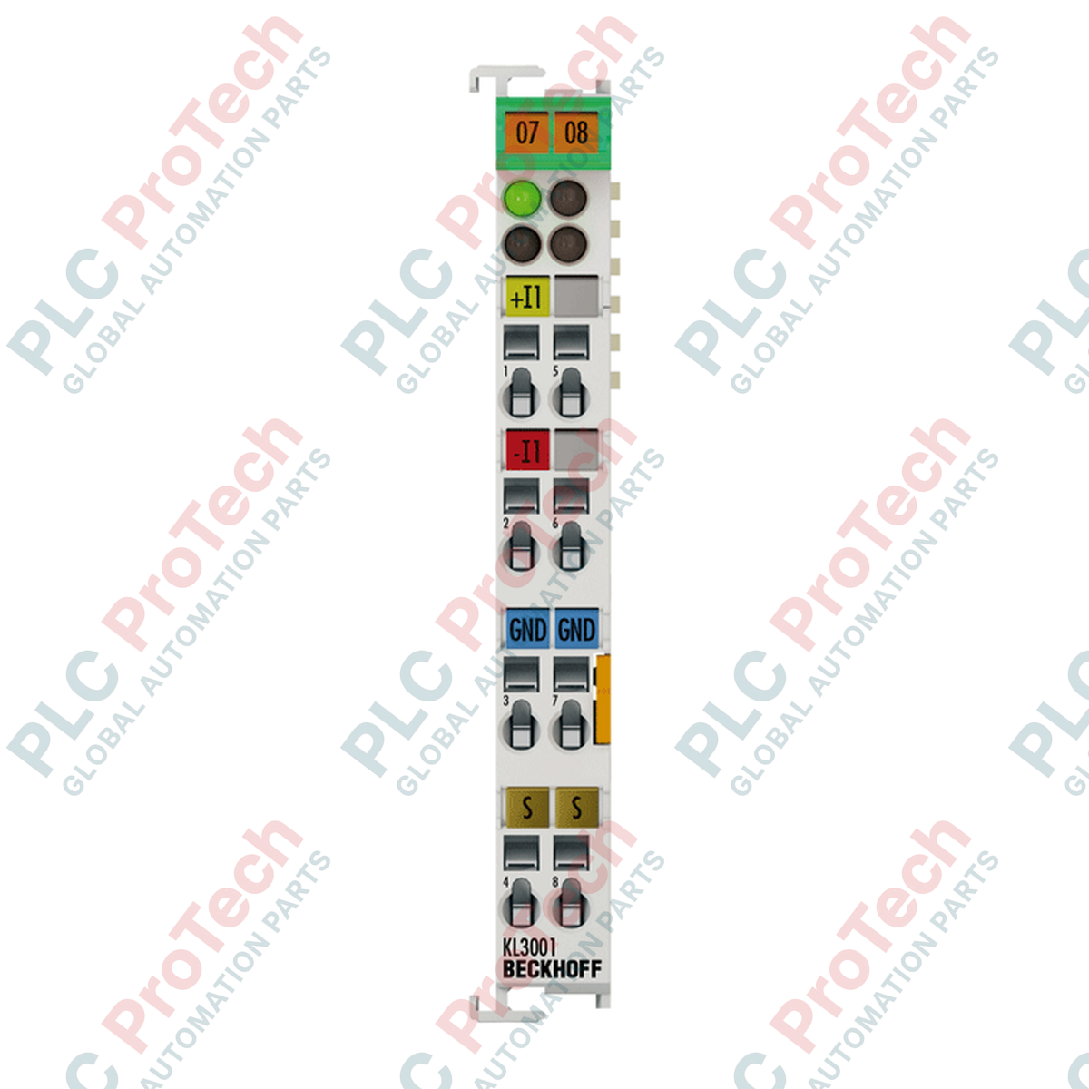
Zur Verarbeitung analoger Differenzsignale innerhalb des Beckhoff I/O-Systems liefert das Beckhoff KS3001 Bus-Terminal hochpräzise Spannungsmessungen im Bereich von -10 bis +10 V. Dieses einkanalige Modul verfügt über ein steckbares Verdrahtungsdesign, das einen schnellen Austausch vor Ort ermöglicht, ohne die Terminalverdrahtung zu stören. Es arbeitet direkt am K-bus und überträgt digitalisierte Messwerte mit elektrischer Trennung an die übergeordnete Steuerung, was es ideal für anspruchsvolle Industrieumgebungen mit zuverlässiger Signalerfassung macht.
Merkmale
- Einkanalige differenzielle Eingangsschaltung für hohe Störfestigkeit.
- Steckbare Verdrahtungsebene (KS-Serie) für werkzeuglosen Terminalaustausch.
- 12-Bit Analog-Digital-Wandlungsauflösung (11 Bit für 0 bis 10 V Bereich).
- Vollständige 500 V elektrische Trennung zwischen K-bus und Signalkreis.
- Direkte Stromversorgung über den K-bus, ohne seitliche Stromkontakte.
- Kompakte 12 mm Gehäusebreite für hochdichte Hutschienenmontage.
Anwendungen
- Differenzielle Spannungsüberwachung in der industriellen Prozesssteuerung.
- Sensorintegration in Prüfständen und Laborautomatisierung.
- Analoge Signalerfassung in elektrischen Hochstörumgebungen.
- TwinCAT-basierte verteilte Steuerungsarchitekturen.
Technische Daten
| Parameter |
Spezifikation |
| Hersteller |
Beckhoff |
| Modell- / Artikelnummer |
KS3001 |
| Anzahl der Eingänge |
1 |
| Signalspannungsbereich |
-10 bis +10 V |
| Eingangstechnologie |
Differenzieller Eingang |
| Innenwiderstand |
typ. > 200 kOhm |
| Gleichtaktspannung (Ucm) |
max. 35 V |
| Auflösung |
12 Bit (11 Bit für 0 bis 10 V Bereich) |
| Umwandlungszeit |
typ. 1 ms |
| Messfehler |
< ±0,3 % (bezogen auf den vollen Messbereich) |
| Elektrische Trennung |
500 V (K-bus / Signalspannung) |
| Stromaufnahme (K-bus) |
typ. 65 mA |
| Prozessbild-Bitbreite |
Eingang: 1 x 16 Bit Daten (1 x 8 Bit Steuerung/Status optional) |
| Anschlussquerschnitt |
Massiv/Feindrähtig: 0,08 bis 1,5 mm², Feindrähtig: 0,14 bis 1,5 mm² |
| Anschlussquerschnitt AWG |
Massiv/Feindrähtig: AWG 28 bis 16, Feindrähtig: AWG 26 bis 16 |
| Abisolierlänge |
9 bis 10 mm |
| Betriebstemperatur |
0 bis +55 Grad Celsius |
| Lagertemperatur |
-25 bis +85 Grad Celsius |
| Relative Luftfeuchtigkeit |
95 %, nicht kondensierend |
| Schutzart |
IP20 |
| Ex-Kennzeichnung |
II 3 G Ex nA IIC T4 Gc |
| Abmessungen (B x H x T) |
12 mm x 100 mm x 68 mm |
| Gewicht |
70 g |
| Versandgewicht (berechnet) |
0,15 kg |
Empirische Ingenieurhinweise
Alternative Modelle & Kompatibilität
Das KS3001 ist die steckbare Verdrahtungsvariante der Standard-KL3001-Busklemme. Obwohl sie identische elektrische Spezifikationen, Registerzuordnungen und TwinCAT-Konfigurationen teilen, verfügt das KS3001 über einen abnehmbaren Anschlussblock. Dies ermöglicht es Wartungsteams vor Ort, ein fehlerhaftes Modul zu ersetzen, ohne die Feldverdrahtung zu trennen, was die Ausfallzeiten in kritischen Prozesskreisen erheblich reduziert.
Anwendungsfallen & technische Hinweise
Überprüfen Sie stets, dass die Gleichtaktspannung (Ucm) zwischen den Differenzeingängen und der internen K-Bus-Masse den absoluten Maximalwert von 35 V nicht überschreitet. Eine Überschreitung dieses Schwellenwerts führt zur Sättigung der Differenzeingangsstufe, was zu abgeschnittenen oder stark ungenauen Messwerten führt und schließlich zu einer dauerhaften Beschädigung der Eingangsoperationsverstärker führen kann.
Inbetriebnahme- & Verdrahtungstipps
Für hochpräzise Anwendungen verwenden Sie geschirmte verdrillte Adernpaare (STP) für die analogen Signalleitungen. Verbinden Sie die Kabelabschirmung mit einem niederohmigen Funktionserde-Schienenanschluss (FE) möglichst nahe am Klemmen-Eintrittspunkt. In TwinCAT kann das Prozessabbild so konfiguriert werden, dass Steuer- und Statusbytes (1x8 Bit) zur Überwachung von Diagnoseflags wie Über- oder Unterbereich enthalten sind.
Installationsrichtlinien
KRITISCHE WARNUNG
Schalten Sie das gesamte Busklemmen-System (sowohl die K-Bus-Stromversorgung als auch alle feldseitigen Spannungen) aus, bevor Sie das KS3001-Modul einstecken, entfernen oder verdrahten. Andernfalls kann es zu elektrischen Lichtbögen, Beschädigungen der internen K-Bus-Kontakte oder zur Korruption des Prozessabbilds benachbarter Klemmen kommen.
1
Montieren Sie die Klemme auf einer standardmäßigen 35 mm DIN-Schiene (nach EN 60715), indem Sie sie auf die Schiene schieben, bis der Verriegelungsmechanismus sicher einrastet.
2
Schieben Sie das Modul seitlich, um es mit den benachbarten Busklemmen zu verbinden, und stellen Sie sicher, dass die Nut- und Federverbindung sowie die seitlichen K-Bus-Kontakte vollständig verbunden sind.
3
Setzen Sie den steckbaren Verdrahtungsblock von vorne in das Anschlussgehäuse ein, bis er einrastet.
4
Verdrahten Sie die Differenzsignal-Leitungen mit einem Schraubendreher, um die Federklemmen zu betätigen. Entfernen Sie die Isolierung der Drahtenden auf 9–10 mm vor dem Einführen.