Description
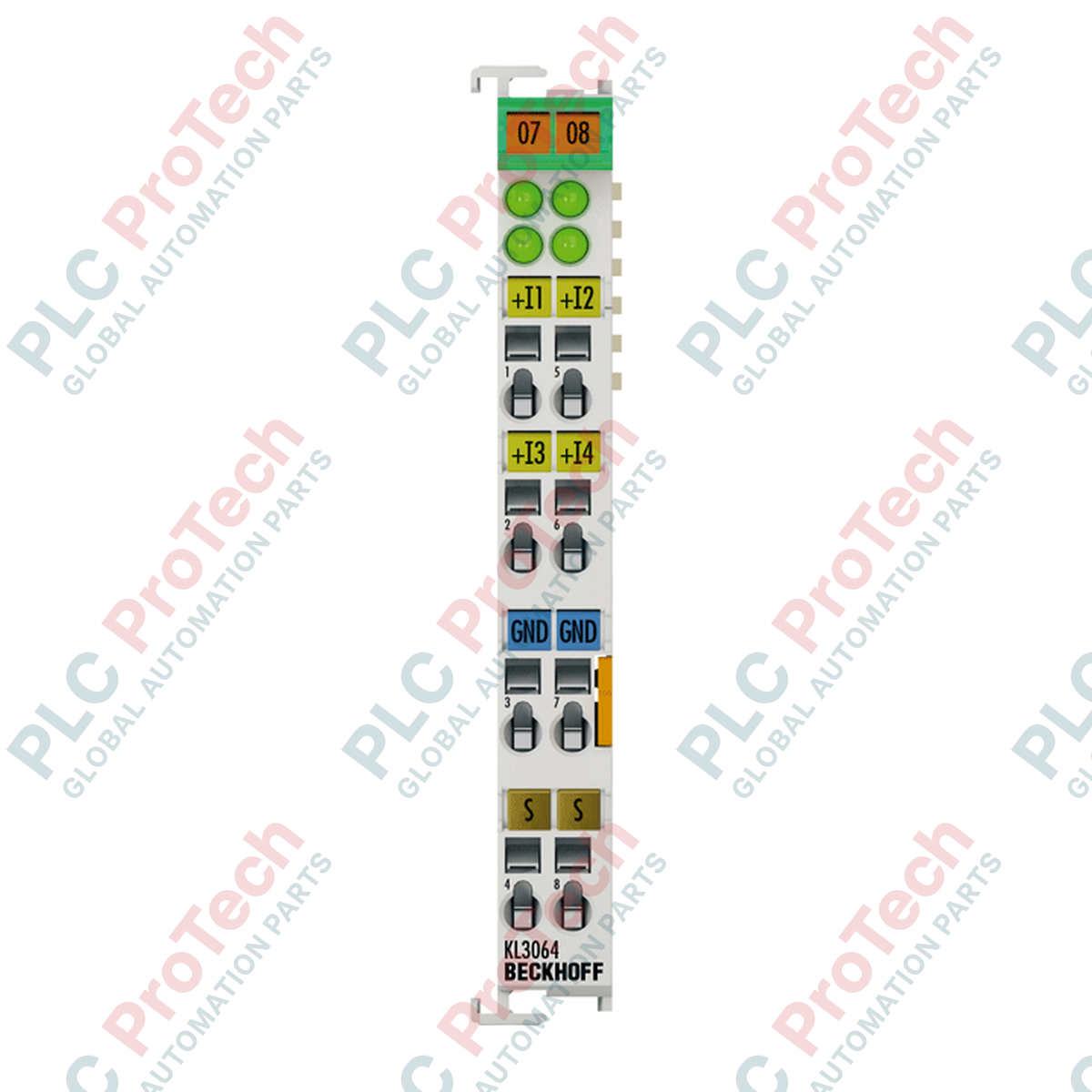
To facilitate precise voltage acquisition in dense processing environments, the Beckhoff KS3064 analog input terminal digitizes field-side signals from 0 to 10 V DC with 12-bit resolution. As part of the premium pluggable KSxxxx series, this 4-channel single-ended module integrates highly reliable performance with a hot-swappable terminal block design, enabling quick hardware change-outs without disturbing existing field wiring. It communicates directly with the primary industrial controller via the standard K-bus interface, combining high processing efficiency with minimal space requirements.
Features
-
Four Single-Ended Inputs: Allows simultaneous monitoring of four independent 0 to 10 V analog signals.
-
Pluggable Wiring Interface: Front-facing tension-clamp connector block is easily removable, reducing maintenance downtime and simplifying cabinet retrofits.
-
12-Bit Analog-to-Digital Conversion: Delivers sharp resolution for highly accurate PLC and DCS monitoring applications.
-
Galvanic Isolation: Provides robust 500 V electrical isolation between the internal K-bus and the process circuitry, defending control hardware from voltage spikes.
-
Compact 12 mm Footprint: Modular housing saves valuable DIN-rail space inside control panels.
Applications
-
Process Sensor Monitoring: Acquires signal inputs from flow meters, pressure transmitters, and distance sensors.
-
HVAC Control Integration: Collects temperature and humidity voltage signals from environmental monitoring units.
-
Machinery Control Platforms: Acts as the analog interface for OEM assembly equipment, handling variable system feedback.
Technical Specifications
| Specification Parameter |
Value / Detail |
| Manufacturer |
Beckhoff |
| Model Number |
KS3064 |
| Module Type |
4-Channel Analog Input (Single-Ended) |
| Signal Voltage Range |
0 to 10 V DC |
| Internal Resistance |
> 200 kOhm (typical) |
| Resolution |
12 bit |
| Conversion Time |
Approx. 4 ms |
| Measuring Error |
< +/- 0.3 % (relative to full scale value) |
| K-Bus Current Consumption |
Typ. 85 mA |
| Electrical Isolation |
500 V (K-bus / signal voltage) |
| Connection Method |
Pluggable spring-actuated terminal block |
| Connection Cross-Section |
Solid/Stranded: 0.08 to 1.5 mm2 (AWG 28 to 16) |
| Operating Temperature Range |
-25 to +60 degC |
| Storage Temperature Range |
-40 to +85 degC |
| Protection Class |
IP20 |
| Ex Marking |
II 3 G Ex nA IIC T4 Gc (ATEX certified) |
| Country of Origin |
Germany |
| Dimensions (W x H x D) |
12 mm x 100 mm x 68 mm |
| Unit Weight |
0.08 kg |
Connections & Interfaces
| Terminal Pin Number |
Signal Type |
Description |
| 1 |
Input 1 (+) |
Voltage input channel 1 (0 to 10 V) |
| 5 |
Input 2 (+) |
Voltage input channel 2 (0 to 10 V) |
| 2 |
Input 3 (+) |
Voltage input channel 3 (0 to 10 V) |
| 6 |
Input 4 (+) |
Voltage input channel 4 (0 to 10 V) |
| 3, 7, 4, 8 |
Common GND |
Internal common reference ground points (0 V) |
Empirical Engineering Insights
Alternative Models & Compatibility
The KS3064 functions identically to the standard KL3064 Bus Terminal. The critical system-level distinction is the physical terminal interface; the KS3064 employs a pluggable terminal system, while the KL3064 utilizes fixed tension clamps. Both share exact software mappings in TwinCAT 2 and TwinCAT 3 systems. If replacing a KL3064, no modifications are required within the PLC configuration.
Application Pitfalls & Engineering Notes
Because this is a single-ended terminal, all 4 input channels share a common internal ground reference linked directly to the system's external ground. If integrating transmitter signals sourced from different, isolated field power supplies, any potential offsets between the power supplies will introduce measurement offset errors. To preserve the 12-bit measurement integrity, ensure that all sensor reference grounds are bonded to a common equipotential earth system.
Commissioning & Wiring Tips
Analog signals in the 0 to 10 V range are highly susceptible to high-frequency electromagnetic interference from surrounding VFDs and power contacts. It is vital to use shielded twisted-pair cabling. Always ground the signal shield only at the central control cabinet ingress plate rather than terminating the shield to the terminal blocks, to avoid creating ground loop currents across the internal K-bus.
Installation Guidelines
CRITICAL WARNING: Completely de-energize the PLC master power and isolate all field connections prior to mounting, dismounting, or pulling the pluggable wiring head from the KS3064 housing. Removing the module or terminal strip under active load can corrupt K-bus communication registers, causing unexpected bus master shutdowns and terminal diagnostic faults.
-
1
Align the KS3064 terminal housing with the 35 mm DIN rail (EN 60715) and push firmly until the locking mechanism clicks audibly.
-
2
Slide the terminal adjacent to the surrounding K-bus modules until the integrated tongue-and-groove side locking tracks slot securely together.
-
3
Insert pre-stripped wire conductors (stripped length: 9 to 10 mm) into the pluggable tension-clamp terminal by depressing the spring actuator latch with a flat-head terminal screwdriver.
-
4
Seat the pluggable terminal connector block firmly into the KS3064 front housing interface until it is fully retained.