Description
Optimized for dynamic high-precision motion profiles, the Delta Electronics ASD-A2-3043-M represents the high-performance tier of the ASDA-A2 Series AC servo drives. This specific controller delivers a 3.0 kW rated output power capability, designed to operate on a 3-phase 400V AC electrical supply network. The "M" configuration suffix designates integrated CANopen communication capabilities alongside a comprehensive built-in electronic cam (E-Cam) functionality, making this drive ideal for complex synchronized multi-axis architectures, high-speed gantries, and closed-loop position matching without relying solely on external motion controller computing power.
Key Features
-
High-Resolution Feedback Compatibility: Fully supports Delta standard 20-bit incremental and absolute encoder systems for high-precision motion tracking.
-
CANopen Communication Protocol: Native CANopen physical interface (M-Type) supporting DS301 network protocols and DSP402 motion profile standards.
-
Full Closed-Loop Interface: Equipped with a secondary CN5 feedback port for direct connection to linear scales or external encoders to eliminate mechanical backlash.
-
Integrated E-Cam Capability: Provides onboard electronic cam control up to 720 points for smooth interpolation, ideal for flying shears and rotary cutters.
-
Suppression Filters: Built-in low-frequency vibration suppression and high-frequency resonance notch filters to safeguard mechanical equipment integrity.
Industrial Applications
- High-speed pick-and-place gantry systems
- Precision CNC machining centers and metal processing machinery
- Flying shear, rotary knife, and multi-axis packaging machinery
- Industrial printing, textile weaving, and winding installations
Technical Specifications
| Manufacturer |
Delta Electronics |
| Model Number |
ASD-A2-3043-M |
| Series |
ASDA-A2 |
| Rated Power Output |
3.0 kW |
| Input Power Supply |
3-Phase 380V to 480V AC (50/60 Hz) |
| Communication Interface |
CANopen / RS-232 / RS-485 |
| Control Mode |
Position Control, Speed Control, Torque Control, CANopen Mode |
| Cooling Method |
Fan Cooling |
| Operating Temperature |
0 to 55 Celsius (without condensation) |
| Weight |
5.5 kg |
| Shipping Weight (Calculated) |
7.0 kg |
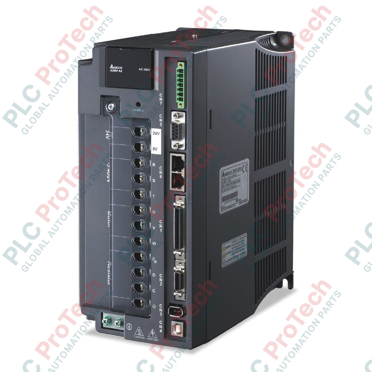
Connections and Interfaces
| Port Reference |
Connector and Interface Assignment |
| CN1 |
Digital and Analog I/O Control Signal Terminal Block (50-pin) |
| CN2 |
Motor Encoder Feedback Port (20-pin quick connector) |
| CN3 |
Serial Configuration Link (RJ45 port for RS-232 and RS-485) |
| CN4 |
Dedicated CANopen Communication Bus Terminals |
| CN5 |
Auxiliary Full-Closed Loop Interface (Direct feedback connection) |
Empirical Engineering Insights
Alternative Models & Compatibility: Transitioning from legacy ASDA-A systems to the ASD-A2 series introduces distinct changes in physical size and pin configuration. When replacing an standard analogue pulse model (e.g., F-type or B-type) with the ASD-A2-3043-M, note that standard digital pulse-train configurations must be adapted to run over the CANopen bus (or the drive must be programmed to run in standalone internal PR/E-Cam mode). Ensure your PLC platform is loaded with the appropriate ASD-A2 EDS configuration file prior to system commissioning.
Application Pitfalls & Engineering Notes: At 3.0 kW output power operating profiles, high-inertia mechanical loads can saturate the internal regenerative resistor quickly under deceleration conditions, precipitating AL005 (Overvoltage) safety trip cycles. In dynamic braking regimes, physically bypass the internal resistor jumper and integrate an external, adequately sized metal-clad brake resistor across terminals P(+) and D.
Commissioning & Wiring Tips: To limit electromagnetic interference from the high-frequency 400V inverter switching cycles, separate the CN1 signal cables and the CN2 encoder feed cables from the motor power line. Implement 360-degree shielding clamps directly to the backplate rather than pigtail grounding paths to avert potential CANopen communication disruption.
Installation Guidelines
CRITICAL SAFETY WARNING
Lethal high-voltage hazards remain active within the internal DC-bus storage capacitors for a duration after input power de-energization. Always verify that the red CHARGE LED indicators on the front panel are completely off and measure DC voltage across terminals P(+) and N(-) to ensure the potential is below 36V DC before touching any electrical terminals.
1
Mount the servo drive vertically on a flat, non-flammable panel backplate to optimize chimney convection airflow currents across the cooling fins.
2
Affix the incoming AC 3-phase mains lines strictly to power input terminals R, S, T. Ensure no live supply paths connect directly to output terminals U, V, W.
3
Ensure a solid electrical ground is constructed via the drive chassis grounding clamp, with resistances matching local installation guidelines.