Description
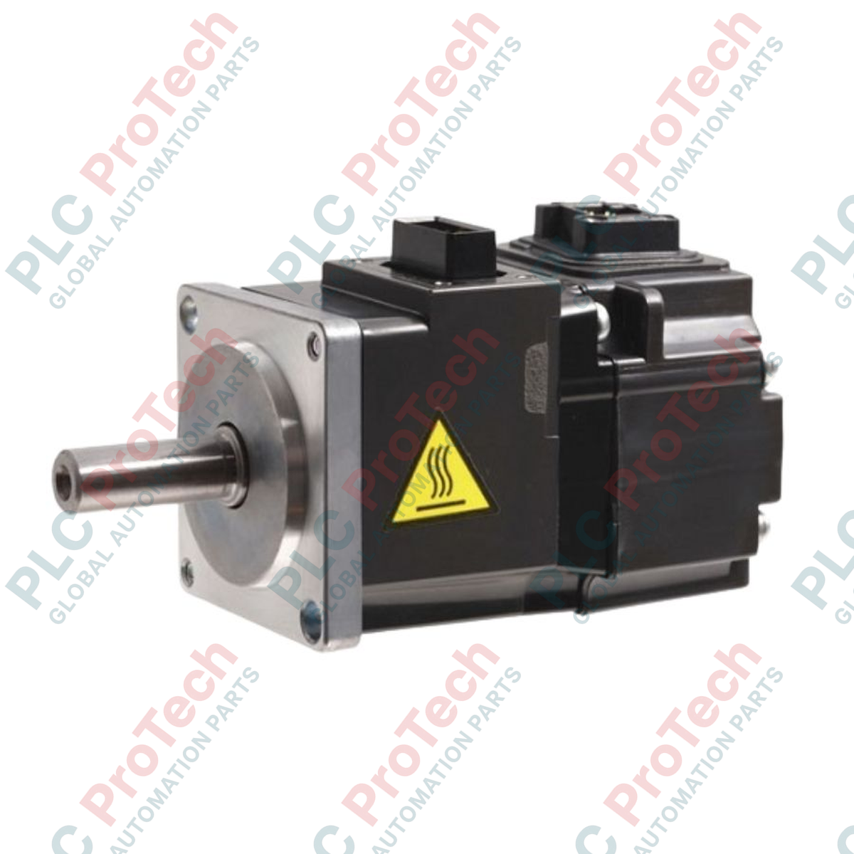
Delivering high-capacity dynamic motion control for demanding heavy-duty positioning systems, the Mitsubishi Electric HA-LFS15K1M is engineered as a high-performance AC servo motor within the advanced MELSERVO-J4 ecosystem. This industrial-grade rotary actuator offers a robust 15 kW power output rating optimized for low-speed, high-torque configurations. Built with a high-resolution absolute encoder, the unit ensures exceptional accuracy, high thermal stability, and reliable integration with multi-axis drive architectures in heavy industrial environments.
Features
-
15 kW High-Capacity Output: Purpose-built for high-torque industrial machinery requiring precise velocity and position control.
-
Optimized Inertia Ratio: Handles a permissible load-to-motor inertia ratio up to 30 times, making it ideal for variable and high-inertia loads.
-
Absolute High-Resolution Encoder: Equipped with native high-density feedback technology to maintain positioning accuracy without relying on manual homing sequences.
-
Robust Thermal Design: Engineered to balance internal heat dissipation efficiently, reducing thermal stress inside control enclosures.
-
Seamless System Integration: Fully compatible with MELSERVO-J4 drive unit platforms via SSCNET III/H or CC-Link IE Field networks.
Applications
- Heavy metal forming, press, and stamping systems.
- Large-scale material handling, gantry systems, and industrial crane hoist controls.
- High-inertia rotary indexing tables and heavy industrial turntables.
- Injection molding machinery and high-clamping force systems.
Technical Specifications
| Parameter |
Value |
| Manufacturer |
Mitsubishi Electric |
| Model Designation |
HA-LFS15K1M |
| Product Range |
MELSERVO-J4 Series |
| Rated Output Capacity |
15 kW |
| Rated Speed |
1000 r/min |
| Permissible Load Inertia Ratio |
30 times motor inertia (maximum) |
| Power Supply Capacity (Recommended) |
22 kVA |
| Cabinet Heat Dissipation (Servo-On) |
640 W (at rated output) |
| Cabinet Heat Dissipation (Servo-Off) |
45 W |
| Required Heat Dissipation Area |
13 m2 |
| Country of Origin |
Japan |
| Shipping Weight (Calculated) |
74.0 kg (163.1 lbs) |
| Package Dimensions (Calculated) |
520 mm x 310 mm x 330 mm |
Connections and Interfaces
| Connection Port / Terminal |
Functional Assignment / Description |
| U / V / W Terminals |
3-phase AC motor power supply inputs from compatible MR-J4 Drive Unit |
| PE Terminal |
Protective Earth / Chassis Grounding connection |
| Encoder Connector |
High-resolution absolute encoder communication interface link to drive unit |
Empirical Engineering Insights
Alternative Models & Compatibility
The HA-LFS15K1M belongs to the medium-to-large capacity class of the MELSERVO-J4 series. Unlike smaller standalone MR-J4-A or MR-J4-B amplifiers, this 15 kW motor must be paired with high-capacity MR-J4-DU15KB or MR-J4-DU15KB-RJ Drive Units. When retrofitting older systems using legacy HA-LP series motors, verify that the physical shaft height, keyway dimensions, and drive firmware are fully updated to support the J4-series high-speed serial encoder communication protocol.
Application Pitfalls & Engineering Notes
Due to the high-inertia load capability of up to 30 times the motor's rotor inertia, manual loop tuning can cause severe mechanical resonance if the parameter settings in Pr. PB06 (Load to motor inertia ratio) and Pr. PB07 (Model loop gain) are misconfigured. For heavy dynamic cycles, an external regenerative braking unit (such as the MR-RB137-F or larger) is highly recommended. Failing to size the regenerative system properly will trigger AL.30 (Regenerative error) or AL.33 (Overvoltage) faults during high-deceleration cycles.
Commissioning & Wiring Tips
To prevent high-frequency electromagnetic interference (EMI) from corrupting encoder tracking data, always install original Mitsubishi double-shielded encoder cables. The encoder shield must be securely clamped to the drive unit ground plate. If noise-induced AL.20 (Encoder normal communication error) or AL.21 (Encoder system error) occur, verify that the PE grounding conductor has low impedance and is routed directly to a centralized, single-point industrial ground bar.
Installation Guidelines
CRITICAL WARNING: HIGH VOLTAGE & RESIDUAL CHARGE
Before performing any installation, wiring, or maintenance on this 15 kW motor, ensure that the primary 3-phase AC power to the drive unit is completely disconnected. Wait at least 20 minutes for the internal bus capacitors to bleed off residual voltage. Verify that the DC bus charge LED on the drive unit is completely extinguished before making contact with the motor power terminals.
1
Securely mount the motor on a rigid, vibration-damping steel foundation. Align the shaft extension precisely with the driven mechanism using a flexible coupling to prevent excessive radial or axial load on the bearings.
2
Connect the 3-phase power supply cables to the U, V, and W terminals. Ensure proper phase matching to prevent uncontrolled reverse rotation during initial drive commissioning.
3
Route the encoder feedback cable separately from the main power and brake lines, maintaining a minimum distance of 300 mm to suppress high-frequency coupling and signal noise.