Description
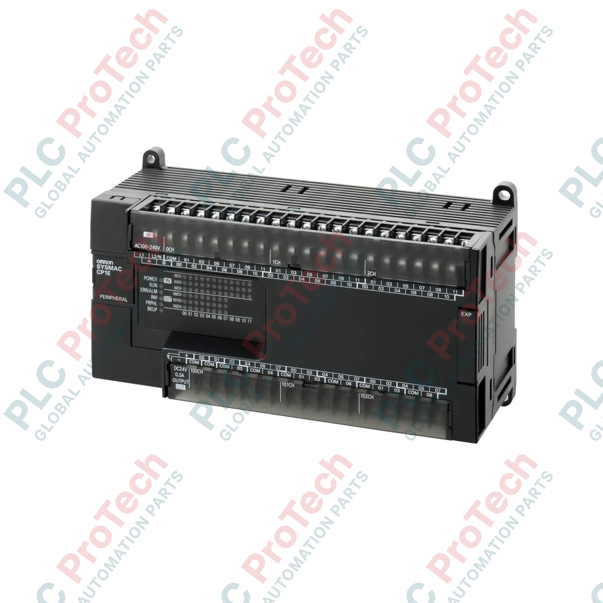
Designed for cost-effective standalone machine automation, the Omron CP1E-E60SDR-A delivers high-density control with integrated physical inputs and outputs in a unified footprint. This basic-type CPU unit simplifies small-scale processes by incorporating 36 DC inputs and 24 relay outputs, minimizing the need for immediate expansion hardware. Equipped with an integrated USB programming interface, this controller is engineered for straightforward commissioning and reliable performance across industrial machinery applications requiring robust, entry-level logic processing.
Features
- High-density physical layout providing 60 built-in I/O channels.
- Integrated USB 2.0 peripheral port for direct connection and programming via CX-Programmer.
- AC-powered input stage compatible with standard plant voltages.
- Relay outputs capable of directly switching moderate current loads.
- Compact, DIN-rail mountable enclosure designed to optimize control panel space.
Applications
- Conveyor and material handling control systems.
- Packaging, wrapping, and labeling machinery.
- Industrial fan, pump, and ventilation sequencing.
- Dedicated municipal water treatment logic panels.
Technical Specifications
| Parameter |
Specification Value |
| Manufacturer |
Omron |
| Model / SKU |
CP1E-E60SDR-A |
| Controller Series |
CP1E (Basic E-type, Renewal S-type) |
| Supply Voltage |
100 to 240 VAC (50/60 Hz) |
| Operating Voltage Range |
85 to 264 VAC |
| Total I/O Points |
60 (36 inputs, 24 outputs) |
| Input Type |
24 VDC inputs (compatible with sink or source sensors) |
| Output Type |
Relay outputs (2 A max per point) |
| Programming Interface |
USB 2.0 (Type-B connector) |
| Unit Dimensions |
190 mm x 90 mm x 78 mm |
| Net Unit Weight |
0.85 kg |
| Shipping Weight (Calculated) |
2.00 kg |
Empirical Engineering Insights
Alternative Models & Compatibility
The CP1E "E" suffix designates a Basic-type architecture. Unlike the "N" (Application) series (such as the CP1E-N60SDR-A), this E-type module lacks built-in RS-232C or RS-485 serial communication ports, option board slots, and analog processing options. Ensure your network requirements do not require serial Modbus or master/slave topologies before deploying this Basic-type variant.
Application Pitfalls & Engineering Notes
Be aware that the CP1E-E60SDR-A does not feature an internal Real-Time Clock (RTC). Logistical steps, automated daily operations, or event logging with standard time-of-day execution cannot be processed natively on this controller. Additionally, when switching highly inductive elements (such as solenoid coils or contactors), external surge suppression (RC snubbers for AC, flyback diodes for DC) must be installed to prevent premature contact wear on the integrated 2 A relays.
Commissioning & Wiring Tips
Verify the connection configuration of your DC inputs. The common terminal can be wired as either sink (NPN) or source (PNP) depending on the 24 VDC polarization. Always earth-ground the Functional Ground (FG) terminal and the Protective Ground (GR) terminal separately to prevent electric noise on the USB connection during online program editing, which can otherwise trigger communications timeouts in CX-Programmer.
Installation Guidelines
CRITICAL WARNING: Isolate all primary and auxiliary AC line voltage sources before mounting, wiring, or handling the CP1E unit. Failure to completely de-energize the incoming supply rails can result in fatal electrical shock, terminal damage, or localized control circuit failures.
1
Mount the CPU unit horizontally on a 35 mm symmetric DIN rail, leaving at least 20 mm of space on both sides and 50 mm above and below for optimal thermal convective airflow.
2
Connect the external AC power supply (100 to 240 VAC) to the L1 and L2 terminals, ensuring proper wire gauge allocation and tight terminal screws. Do not connect power to the physical I/O terminals.
3
Establish the common connections for physical sensors on the digital input block, then connect field outputs to the relay terminals following correct polarity constraints.
4
Apply main system power, establish connection with CX-Programmer using a standard shielded USB cable, and run diagnostics to confirm zero hardware system faults (ERR/ALM LED remains off).