Description
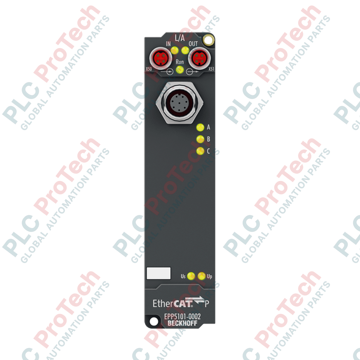
Designed for direct field deployment in decentralized architectures, the Beckhoff EPP5101-1002 provides a high-performance interface for incremental encoders using RS422 differential or TTL single-ended signals. This robust IP67-rated module is part of the EtherCAT P system, merging high-speed communication and power delivery into a single, unified cable. By processing differential signals (A, B, C) directly on the machine, the module eliminates long analog wiring runs and significantly reduces electromagnetic interference (EMI) risks in demanding industrial installations.
Features
-
Universal Encoder Interface: Supports RS422 differential, TTL single-ended, counter, and pulse generator modes.
-
EtherCAT P Cabling: Combines EtherCAT communication and dual power supplies (Us for system/sensors, Up for peripherals) into a single, P-coded M8 connector.
-
High-Speed Processing: Features a limit frequency of up to 1 MHz, matching 4 million increments per second with 4-fold evaluation.
-
Distributed Clocks: Native support for synchronized sub-microsecond system timestamping.
-
Industrial Protection: IP65, IP66, and IP67 sealed zinc die-cast housing for screw-mounting directly on machine frames without an electrical cabinet.
Applications
-
Precision Motion Control: Real-time positioning feedback in packaging machinery and material handling systems.
-
Rotary and Linear Feedback: direct interfacing to high-resolution quadrature encoders on servo axes.
-
Harsh Environment Mounting: Distributed I/O setups in food processing, washdown areas, and automotive assembly lines.
Technical Specifications
| Parameter |
Value |
| Manufacturer |
Beckhoff |
| Model Number |
EPP5101-1002 |
| Protocol |
EtherCAT |
| Bus Interface |
2 x M8 socket, shielded, screw type, P-coded |
| Connection Technology |
M12, 8-pin, screw type (A-coded) |
| Number of Channels |
1 |
| Encoder Signals |
A, A (inv), B, B (inv), C, C (inv) differential inputs |
| Encoder Operating Voltage |
24 V DC / 0.5 A (derived from Us supply) |
| Nominal Voltage |
24 V DC (-15% / +20%) |
| Counter Capacity |
16 or 32 bit, binary |
| Limit Frequency |
1 MHz (4 million increments/s with 4-fold evaluation) |
| Current Consumption (Us) |
Typically 100 mA |
| Electrical Isolation |
500 V RMS |
| Operating Temperature |
0 to 55 degC |
| Storage Temperature |
-25 to 85 degC |
| Protection Class |
IP65/66/67 (conforms to EN 60529) |
| Country of Origin |
Germany |
| Shipping Weight (Calculated) |
0.5 kg |
| Package Dimensions (Calculated) |
150 x 50 x 50 mm |
Connections and Interfaces
| M12 Pin |
Signal Assignment |
Function |
| 1 |
A |
Encoder Channel A (Non-inverted Input) |
| 2 |
A (inv) |
Encoder Channel A (Inverted Input) |
| 3 |
B |
Encoder Channel B (Non-inverted Input) |
| 4 |
B (inv) |
Encoder Channel B (Inverted Input) |
| 5 |
C / Zero |
Latch/Zero-Pulse Input (Non-inverted) |
| 6 |
C (inv) |
Latch/Zero-Pulse Input (Inverted) |
| 7 |
GND |
Reference Ground for Encoder Power |
| 8 |
+24 V DC |
Auxiliary Encoder Sensor Supply Output |
Empirical Engineering Insights
Alternative Models & Compatibility
The EPP5101-1002 is specifically built for EtherCAT P (P-coded physical interface). Note that it cannot be plugged directly into standard EtherCAT (EP5101-0002) networks without the use of an EP9224 or EP9214 junction box, which breaks out communication and the respective Us/Up power lines. TwinCAT 3 requires standard ESI file updates to correctly recognize the EPP series hardware versions.
Application Pitfalls & Engineering Notes
When configuring downstream EtherCAT P nodes, verify that the total cumulative current drawn from the Us (system/sensor power) loop does not exceed the line thresholds. High-resolution, multi-channel linear encoders can cause significant voltage drops across long M8 P-coded link lines, triggering under-voltage fault codes in TwinCAT.
Commissioning & Wiring Tips
To ensure stable 1 MHz count operations, utilize double-shielded twisted-pair cabling for all differential M12 encoder runs. Standard single-ended TTL encoders are more susceptible to ambient motor-drive noise; hence, we highly recommend terminating the cable shield completely 360 degrees around the metallic M12 plug shell.
Installation Guidelines
CRITICAL WARNING:
Isolate all electrical power sources before handling, installing, or servicing EtherCAT P physical connectors. Ensure the field cables are not under load during coupling to prevent arcing and connector degradation on the sensitive P-coded gold pins.
1
Mount the module on a flat machine surface using standard M3 screws. Ground the mounting tabs directly to the frame to ensure maximum EMI immunity.
2
Connect the incoming EtherCAT P M8 cable to the P-coded input socket, hand-tightening to IP67 specifications (typically 0.4 Nm torque).
3
Install the M12 encoder interface cable to the bottom connection port. Protect any unused M8 or M12 interfaces with industrial plastic dust caps to preserve the IP67 housing seal integrity.