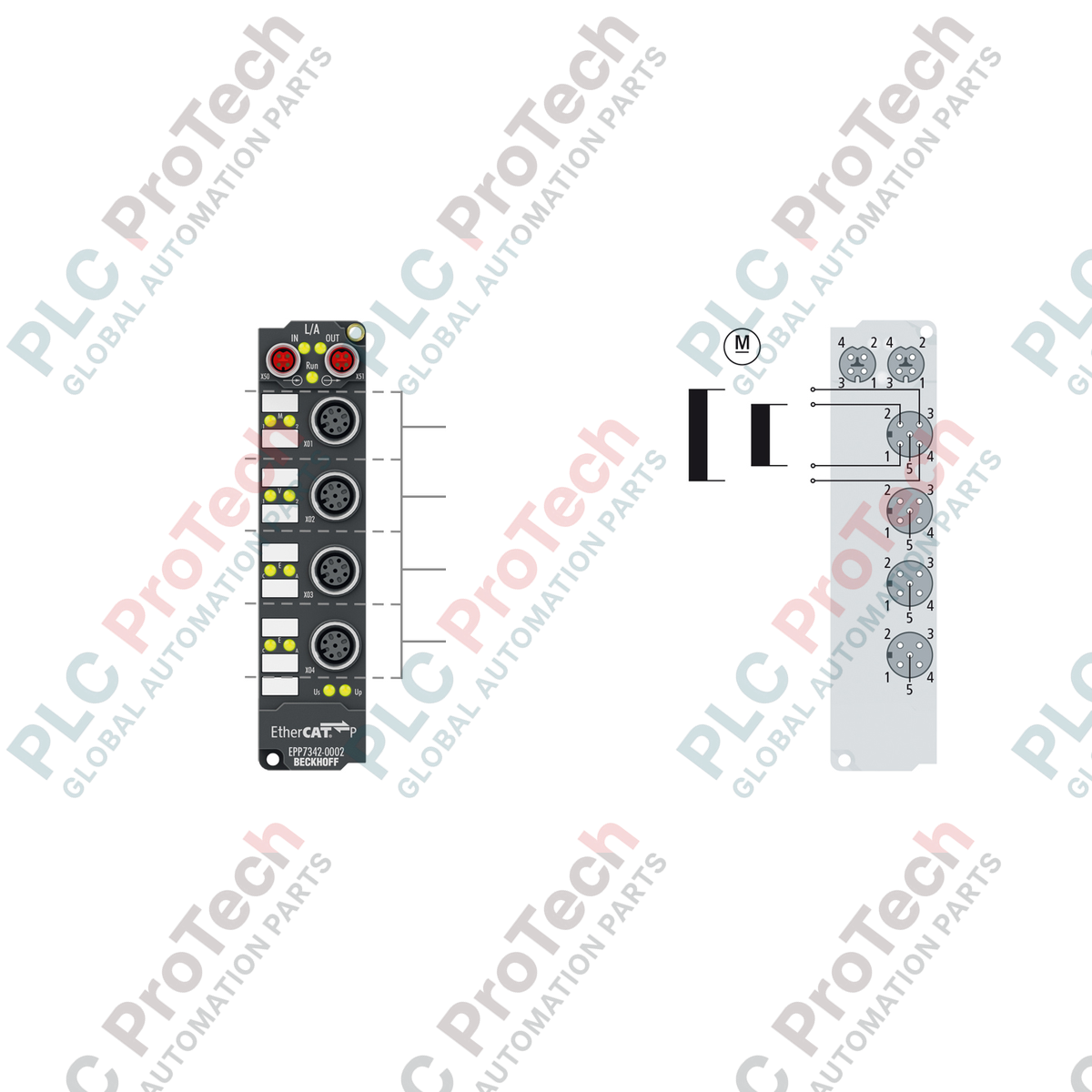
Description
Decentralized motion control in demanding environments is efficiently handled by the BECKHOFF EPP7342-0002, a rugged, dual-channel DC motor output stage designed directly for field installation. This high-performance EtherCAT P Box integrates dual-channel drive control for small DC brush motors with built-in incremental encoder inputs, facilitating closed-loop positioning directly on the machine frame. By utilizing EtherCAT P technology, the device combines ultra-fast communication and power supply (both system/sensor voltage US and peripheral power for actuators UP) into a single, standardized M8 connection, drastically reducing cabling complexity, weight, and installation footprints in modular machine designs.
Features
- Dual-channel DC brush motor control with integrated travel distance control functionality.
- Dynamic 32 kHz PWM clock frequency utilizing a 180-degree phase shift to minimize peak currents and reduce electromagnetic emissions.
- Built-in incremental encoder feedback interface for precise speed, velocity, and positioning feedback loops.
- Fully short-circuit-proof output stages with a common thermal overload warning system mapped directly to the controller.
- Integrated Distributed Clocks (DC) support, allowing synchronization with microsecond precision across the EtherCAT network.
- High environmental protection rating (IP65/66/67) for direct machine mounting without requiring protective electrical enclosures.
Applications
- Decentralized conveyor drive systems, sorting mechanisms, and divert gates in high-throughput logistics.
- Format adjustments, motorized guide positioning, and automated tooling alignment in packaging machinery.
- Intralogistics drive units, automated guided vehicles (AGVs), and compact transfer shuttles.
- Distributed auxiliary motion axes in packaging, printing, and automated assembly cells.
Technical Specifications
| Parameter |
Specification Value |
| Manufacturer |
BECKHOFF |
| Model Number |
EPP7342-0002 |
| Product Series |
EtherCAT P Box (EPP) |
| Protocol |
EtherCAT |
| Number of Channels |
2 Outputs |
| Rated Load Voltage |
8 to 48 V DC |
| Load Type |
DC brush motor, inductive loads |
| Output Current |
Max. 3.5 A per channel (short-circuit proof) |
| Duty Factor |
0 to 100% (voltage-controlled) |
| Internal Resolution |
Max. 10-bit current, 16-bit speed |
| Electrical Isolation |
500 V |
| Current Consumption (from US) |
Typ. 100 mA |
| Housing Material |
PA6 Polyamide |
| IP Rating |
IP65, IP66, IP67 (conforms to EN 60529) |
| Operating Temperature |
-25 to +60 degC |
| Storage Temperature |
-40 to +85 degC |
| Dimensions (W x H x D) |
30 mm x 126 mm x 26.5 mm |
| Weight |
Approx. 165 g |
| Shipping Weight (Calculated) |
2.0 kg (packaged) |
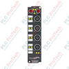
Connections and Interfaces
| Connector Type |
Connection Assignment |
| Bus Interface (2 x M8) |
Screw type, shielded, P-coded (EtherCAT P input and output loop) |
| Motor Connection (M12) |
M12 x 1, 5-pin, A-coded (DC output and feedback signals) |
| Housing Sockets |
Integrated 8 x M8 and 4 x M12 interfaces |
Empirical Engineering Insights
Alternative Models & Compatibility
The EPP7342-0002 utilizes EtherCAT P, meaning it cannot be used directly in traditional standard EtherCAT (EP series) chains without a dedicated junction or feed-in box (such as the EP9224-0037). Ensure that your TwinCAT configuration files (ESI) are updated to match the EtherCAT P device profile to ensure hassle-free integration and scanning in the TwinCAT system manager.
Application Pitfalls & Engineering Notes
When sizing DC motors, pay close attention to the 3.5 A limit per channel. If both output stages trigger thermal overload concurrently, the module reports a common thermal overload warning. When running inductive loads or motors with high regenerative energy on deceleration, external transient voltage suppression must be planned if the returned energy exceeds the absorption capabilities of the system power supply line.
Commissioning & Wiring Tips
Proper grounding of the fieldbus shielding is imperative. Always use pre-assembled, fully shielded M8 P-coded cabling for the EtherCAT P line to prevent noise injection from adjacent high-voltage motor cables. The encoder lines must also be shielded and routed away from high-noise AC lines to maintain continuous signal integrity during operation.
Installation Guidelines
CRITICAL WARNING
Before starting any mounting, connection, or service procedures on the module, ensure that the power supply of the entire EtherCAT P segment is completely de-energized. Verify the system has bled residual electrical charges. Failure to isolate power can result in transient arcs, damage to the internal output stages, or permanent controller disruption.
1
Securely mount the EtherCAT P Box to a flat, stable surface using the two integrated 3.5 mm mounting holes designed for M3 screws.
2
Connect the incoming EtherCAT P cable to the M8 input socket (P-coded) and connect the outgoing cable to the subsequent downstream box.
3
Ensure unused M8 and M12 sockets are sealed with official IP67 protective caps to prevent moisture, dust, and contaminant ingress.
4
Connect the motor outputs and incremental encoder lines, verifying the pin alignment against your machine schematic before energizing.