Description
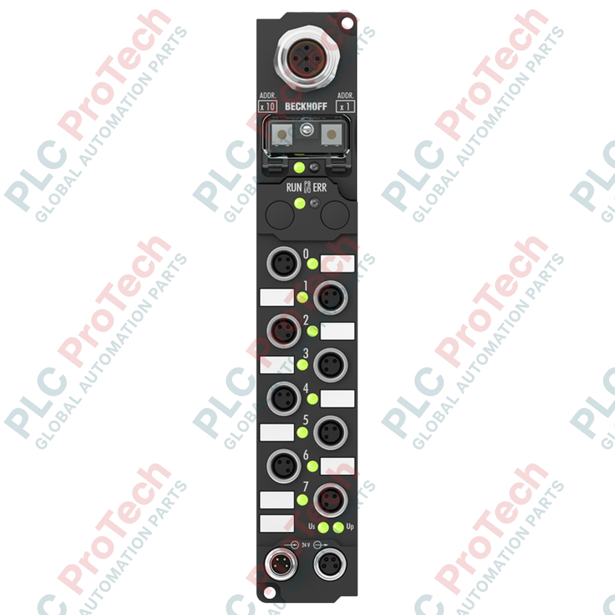
Facilitating direct decentralization of machine sensor logic, the Beckhoff IP1001-B730 functions as a ruggedized 8-channel digital input interface designed for direct on-machine installation without control cabinets. This Fieldbus Box connects standard 24 V DC digital sensors via compact M8 screw connectors and transmits state data over Modbus RTU or Modbus ASCII networks. Devoid of complex sub-bus systems, the unit integrates functional input acquisition directly into demanding environments, achieving high vibration resistance and complete mechanical enclosure protection.
Features
-
Direct Machine Mounting: IP65, IP66, and IP67 protection ratings eliminate the need for traditional terminal boxes or protective enclosures.
-
Deterministic Signal Processing: 8 digital inputs with a fixed 3 ms hardware filter time to suppress physical contact bounce and electromagnetic line interference.
-
Modbus RTU/ASCII Compliance: Integrated 5-pin M12 (B-coded) interface supporting transmission speeds up to 38,400 baud.
-
Local Diagnostics: Independent status LEDs for network activity, bus errors, module power, and individual I/O channel states.
-
Daisy-Chained Power Architecture: Dual M8 power connectors allow looped feeding of control voltage to adjacent Fieldbus Box nodes.
Applications
- Decentralized assembly lines and sorting conveyors in automotive packaging plants.
- Harsh chemical processing and wastewater treatment facilities requiring high liquid ingress protection.
- Pneumatic sensor distribution blocks on heavy machinery and robotic arm end-effectors.
Technical Specifications
| Specification Parameter |
Technical Value / Rating |
| Manufacturer |
Beckhoff Automation |
| Model Number |
IP1001-B730 |
| Protocol / Interface |
Modbus RTU / Modbus ASCII (RS485) |
| Bus Interface Connection |
1 x M12 socket, 5-pin, B-coded |
| Baud Rates Supported |
150, 300, 600, 1200, 2400, 4800, 9600, 19200, 38400 baud |
| Digital Inputs |
8 channels, 24 V DC |
| Input Filter Time |
3.0 ms |
| Control Supply Voltage |
24 V DC |
| Power Feed Connector |
1 x M8 male, 4-pin |
| Power Downstream Connector |
1 x M8 female, 4-pin |
| Internal Box Current Draw |
45 mA (excluding sensor draw, max. 0.5 A) |
| Electrical Isolation |
500 V (Control voltage to fieldbus) |
| IP Protection Class |
IP65 / IP66 / IP67 (conforms to EN 60529) |
| Operating Temperature Range |
0 to +55 degC |
| Storage Temperature Range |
-25 to +85 degC |
| Standards & Compliance |
EN 60068-2-6 (Vibration), EN 60068-2-27 (Shock), CE, UL |
| Weight |
210 g (0.46 lbs) |
| Shipping Weight (Calculated) |
0.50 kg (Includes protective industrial packaging) |
| Country of Origin |
Germany |
Connections and Interfaces
| Interface Connection |
Pin Configuration |
Function Assignment |
| Power Feed (M8 Male, 4-Pin) |
Pin 1 |
Feed control voltage Us, +24 V DC |
| Pin 2 |
Feed auxiliary/load voltage Up, +24 V DC |
| Pin 3 |
GNDs (Control voltage ground reference) |
| Pin 4 |
GNDp (Auxiliary/load voltage ground reference) |
| Modbus RTU (M12, 5-Pin B-Coded) |
Pin 1 |
Shield (FE) |
| Pin 2 |
RxD/TxD-A (RS485 Negative data line) |
| Pin 3 |
DGND (Modbus internal reference ground) |
| Pin 4 |
RxD/TxD-B (RS485 Positive data line) |
| Pin 5 |
Not Connected |
Empirical Engineering Insights
Alternative Models & Compatibility
The IP1001-B730 uses a direct Modbus interface. Users of Beckhoff Lightbus or PROFIBUS systems should source the IP1001-B310 or IP1001-B200 variants respectively. Physical mounting dimensions and M8 sensor mapping are identical across these model variations, easing cross-protocol mechanical retrofits. Note that firmware modifications in the master host PLC are required if migrating to a different fieldbus family.
Application Pitfalls & Engineering Notes
To guarantee IP67 execution, all unused M8 and M12 connection ports must be covered with industrial threaded brass protective caps. Leaving ports uncapped breaches the physical seal, risking internal galvanic tracking and permanent component failure from condensation. Additionally, ensure the total combined current of sensors connected to the module does not exceed 0.5 A to prevent safety shutdown or thermal loading of the internal bus coupler.
Commissioning & Wiring Tips
The Modbus address is established via two rotary address switches located under the physical screw-cover cap on the side of the module. Setting changes only take effect after power cycling the unit. Always activate a termination resistor (120 Ohm) on the last physical node of the Modbus segment. Use the Beckhoff KS2000 serial programming software interface to easily monitor active data frames and calibrate custom communication filter limits if standard parameters are insufficient.
Installation Guidelines
CRITICAL WARNING: De-energize all primary field power systems and secondary control voltages before mounting, connecting, or configuring the field module. Physical work on live electrical interfaces can trigger unpredictable machine behaviors, contact degradation, or dangerous short-circuits.
1
Securely bolt the Fieldbus Box to a flat machine surface using two standard M3 screws, avoiding areas exposed to constant abrasive spray or direct thermal radiation.
2
Unscrew the protective side cover and adjust the node ID using the integrated rotary switches to define the unique Modbus station address.
3
Tighten all sensor and power cabling connectors using manual force or calibrated torque wrenches (max. 0.4 Nm for M8, 0.6 Nm for M12) to secure the sealing ring against dust and water.
4
Perform a dry-run test to verify that the integrated network LEDs light up and signal proper Modbus host status before running live production logic.