Description
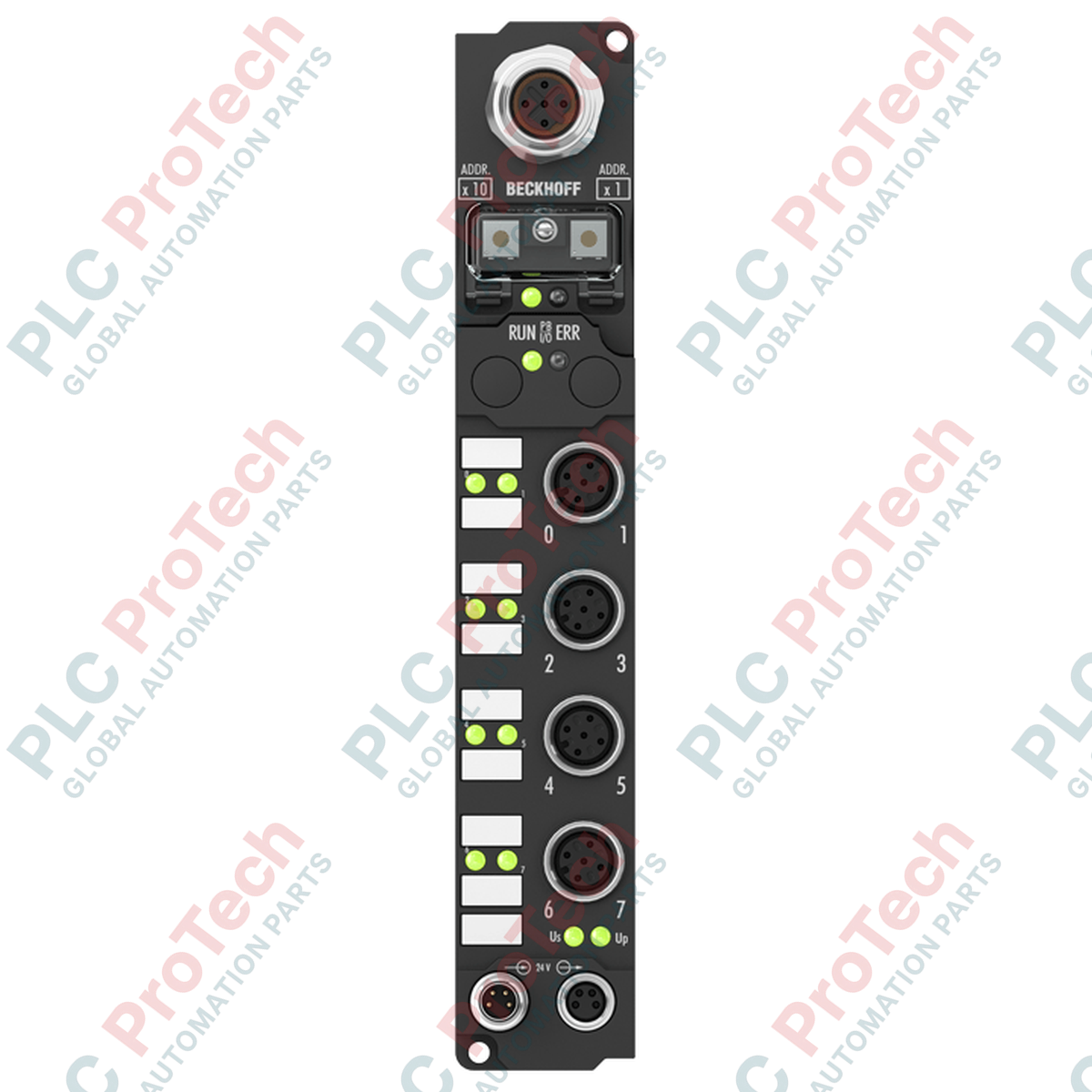
Decentralized operational architectures benefit from the robust physical and electrical design of the Beckhoff IP2302-B800 fieldbus interface unit. This system integrates high-density digital I/O capabilities directly at the machine level, eliminating the need for expensive electrical enclosures. Operating via an RS485 interface, this module enables reliable serial communications across extended distances in high-noise industrial environments. With 4 digital inputs featuring a 3 ms input filter and 4 digital outputs delivering up to 0.5 A per channel, the unit provides a balanced local control solution for sensors and actuators utilizing standard M12 connection technology.
Features
-
Dual-Directional I/O Configuration: Equipped with 4 digital inputs and 4 digital outputs to manage local field sensors and actuators from a single station.
-
Serial Communication Interface: Integrated RS485 physical layer provides stable data transmission over long physical distances in high-interference settings.
-
Optimized Input Filtering: Input hardware includes a 3 ms hardware filter to prevent false triggers from mechanical switch bounce and electrical noise.
-
Short-Circuit Protected Outputs: High-side 24 V DC outputs deliver up to 0.5 A of continuous current, protected against overload and thermal faults.
-
Robust IP67 Protection: Fully sealed enclosure designed to withstand moisture, dust, and direct liquid washdowns without secondary protective housings.
Applications
-
Automotive Assembly Lines: Direct mounting on mechanical structures for localized proximity sensor and pneumatic valve routing.
-
Conveyor and Material Handling Systems: Direct control of sorters, divert gates, and photo-eye sensors over long RS485 bus runs.
-
Packaging Machinery: Compact field deployment on rotary indexes and fast-moving indexing tables where cabinet space is unavailable.
Technical Specifications
| Parameter |
Specification Value |
| Manufacturer |
Beckhoff Automation GmbH & Co. KG |
| Model Reference |
IP2302-B800 |
| Fieldbus Interface |
RS485 |
| Digital Inputs |
4 channels (24 V DC) |
| Input Filter Time |
3 ms |
| Digital Outputs |
4 channels (24 V DC, short-circuit protected) |
| Max. Output Current |
0.5 A per channel |
| I/O Connection Method |
M12 connector (screw-type lock) |
| Operating Temperature |
0 to 55 degC |
| Storage Temperature |
-25 to 85 degC |
| Protection Class |
IP67 (when all unused ports are sealed) |
| Country of Origin |
Germany |
| Shipping Weight (Calculated) |
2.0 kg (including protective packaging) |
Empirical Engineering Insights
Alternative Models & Compatibility
The IP2302-B800 belongs to the legacy Beckhoff Fieldbus Box architecture. When integrating this module into newer EtherCAT networks, a gateway or a corresponding coupler (such as the EP-series Fieldbus Boxes) should be selected unless native RS485 communication interfaces are already established in your PLC control system. Note that firmware addressing parameters are set via physical rotary switches on the side of the housing; preserve these settings when swapping old hardware for new replacements.
Application Pitfalls & Engineering Notes
While the outputs are rated for 0.5 A individually, engineers must calculate the total aggregate load current flowing through the control box. Exceeding the internal thermal limitations will trip the integrated thermal shutdown mechanisms. Additionally, when long RS485 cable runs are deployed alongside high-voltage motor cables, induced transient voltages can corrupt serial frame packets. Maintaining physical separation of signal and power lines is critical.
Commissioning & Wiring Tips
For RS485 communication stability, ensure that a 120-Ohm termination resistor is physically installed at the absolute start and end points of the communication segment. Always use shielded, twisted-pair cabling specifically certified for RS485 network protocols. Ground the shield at a single central point to prevent circulating ground loops that can degrade signal integrity.
Installation Guidelines
CRITICAL WARNING: Prior to attempting hardware installation, commissioning, or physical swap-outs, ensure all auxiliary power supplies (both the logic control power and actuator output load power lines) are completely de-energized. Confirm that zero voltage is present across all terminal lines to prevent damage to the sensitive serial communication driver circuitry.
1
Mechanical Mounting: Mount the Fieldbus Box securely onto a flat, vibration-dampened structural surface using two M4 bolts. Ensure the mounting plane is even to prevent physical stress on the housing.
2
Configure Network Node Address: Set the unique node address using the hardware rotary coding switches under the protective screw cap. Secure the protective cap tightly after configuration to maintain the IP67 ingress seal.
3
Fieldbus Connection: Route and secure the RS485 communication line to the designated M12 fieldbus connector port. Hand-tighten the M12 screw rings to ensure a fully dust- and water-tight interface.
4
Power & I/O Cabling: Connect the 24 V DC supply and individual local sensors/actuators. Seal all unused M12 ports with industrial-grade protective caps to prevent environmental contamination and moisture ingress.