Description
Interfacing field instruments with standard PLC process control systems requires reliable, noise-resistant signal conversion. The Beckhoff KS4494 Bus Terminal integrates physical analog measurement and signal output capabilities into a single, space-saving 12 mm housing module. Operating directly on the standard K-bus backplane, this module provides dual-channel analog inputs and dual-channel analog outputs configured for bipolar -10 to +10 V single-ended signaling. Its distinct pluggable wiring interface enables rapid, error-free wiring field assembly and hot-swappable terminal block replacements without disturbing permanent control cabinet wiring connections.
Key Technical Features
-
Dual-Function Assembly: Houses 2 analog inputs and 2 analog outputs within a unified physical terminal channel structure.
-
Bipolar Voltage Range: Configured for high-precision -10 to +10 V signal ranges, optimizing control for actuators and bi-directional sensors.
-
Pluggable Wiring Level: Tool-less terminal block detachment design simplifies on-site hardware maintenance cycles.
-
Electrical Isolation: Features 500 V galvanic isolation between the internal K-bus and the field-side analog circuits.
-
Efficient Power Sourcing: Low typical current consumption of 70 mA directly from the K-bus internal logical supply line.
Industrial Applications
-
Proportional Valve Control: Standard interfacing for industrial hydraulics and pneumatic positioners requiring bipolar signal drives.
-
Closed-Loop Speed Control: Synchronizing feedback from variable frequency drives (VFDs) and positioning tachometers.
-
OEM Machine Integration: Compact multi-channel signal routing inside standard manufacturing cells with restricted installation footprint.
-
HVAC Damper Actuation: Controlling electronic draft dampers and air handler systems using standard voltage loops.
Technical Specifications Table
| Parameter Name |
Value Specification |
| Manufacturer |
Beckhoff Automation GmbH & Co. KG |
| Model Designation |
KS4494 |
| Terminal Style |
Pluggable connection level (KS Series) |
| Input / Output Count |
2 Analog Inputs / 2 Analog Outputs |
| Analog Signal Type |
Single-ended, -10 to +10 V |
| Resolution |
12-bit binary |
| Conversion Time |
< 2 ms |
| Output Error Margin |
< +/-0.3% (relative to full scale) |
| Internal Input Resistance |
> 130 kOhm |
| Output Load Limit |
> 5 kOhm (short-circuit proof) |
| Current Draw (K-Bus) |
typ. 70 mA |
| Isolation Voltage |
500 V (K-bus to signal potential) |
| Conductor Connection Type |
Spring-actuated cage clamps |
| Wire Cross-Section |
Solid/Stranded: 0.08...1.5 mm2 (AWG 28...16) |
| Housing Material |
Polycarbonate, flame-retardant |
| Operating Temperature |
0 to +55 degC |
| Dimensions (W x H x D) |
12 mm x 100 mm x 68 mm |
| Net Module Weight |
0.055 kg |
| Shipping Weight (Calculated) |
2.00 kg (with reinforced industrial protective packaging) |
| Country of Origin |
Germany |
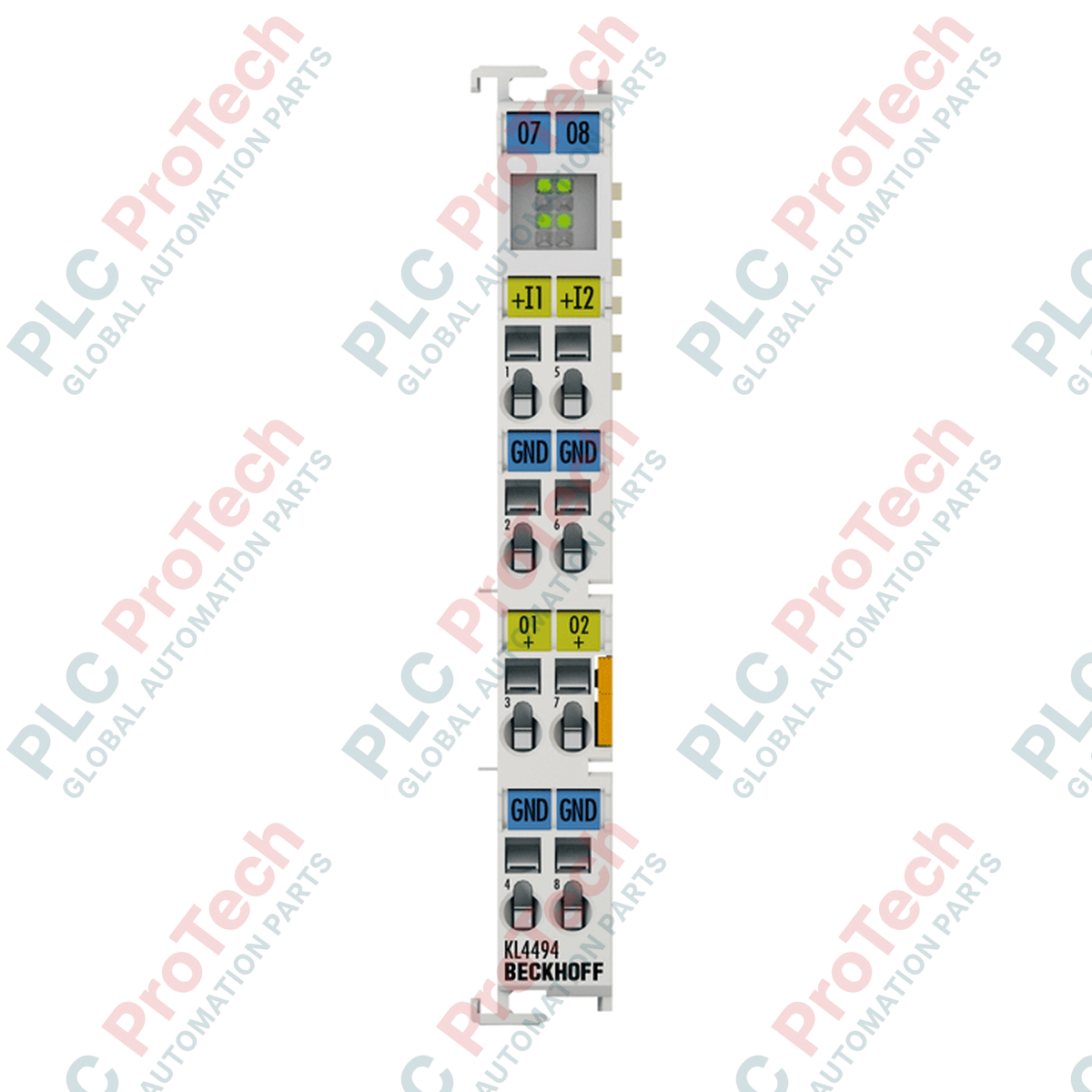
Connections and Interfaces
| Terminal Contact Point |
Signal Assignment |
Functional Circuit Details |
| Contact 1 |
Input 1 (+) |
Analog input channel 1 signal line (-10 to +10 V) |
| Contact 2 |
Output 1 (+) |
Analog output channel 1 control line (-10 to +10 V) |
| Contact 3 |
0 V (Input 1 Ref) |
Common reference return path for Input 1 |
| Contact 4 |
0 V (Output 1 Ref) |
Common reference return path for Output 1 |
| Contact 5 |
Input 2 (+) |
Analog input channel 2 signal line (-10 to +10 V) |
| Contact 6 |
Output 2 (+) |
Analog output channel 2 control line (-10 to +10 V) |
| Contact 7 |
0 V (Input 2 Ref) |
Common reference return path for Input 2 |
| Contact 8 |
0 V (Output 2 Ref) |
Common reference return path for Output 2 |
Empirical Engineering Insights
Alternative Models & Compatibility
The KS4494 serves as the direct physical drop-in equivalent to the standard Beckhoff KL4494 bus terminal block. While the KL4494 utilizes static cage clamps, the KS4494 integrates a split, multi-pin pluggable front interface. Both terminals share the exact same TwinCAT XML device description (GSDML/EDS configurations) and use identical 2 x 16-bit input and 2 x 16-bit output process images, requiring zero modifications to controller logic during hardware modernization programs.
Application Pitfalls & Engineering Notes
Because this module utilizes a single-ended signal configuration with internal reference ground links, field instrumentation sharing common paths can introduce signal skewing. When routing cables across long industrial enclosures, ground loops might compromise the 12-bit ADC digitization stability. Ensure external transmitters and current loads share a zero-volt potential close to the terminal group or deploy isolation barriers if signal noise spikes are detected in TwinCAT Scope.
Commissioning & Wiring Tips
Use a standard 3.0 mm flat-head terminal screwdriver to actuate the spring contacts. We highly recommend using shielded twisted pair (STP) cabling for all -10 to +10 V connections, grounding the shield exclusively at the cabinet side's main grounding busbar. During initial startup, map variables within TwinCAT to monitor the raw register values, where standard hexadecimal limits represent the bipolar physical boundaries.
Installation Guidelines
CRITICAL SYSTEM INTEGRITY WARNING
Always isolate all field-side and logic-side power supplies before mounting, dismounting, or inserting/extracting the pluggable terminal blocks. Failure to de-energize the K-bus backplane can lead to physical arc damage or disrupt adjacent backplane communications, triggering a bus controller watchdog shutdown.
1
Align the slide-and-key guide mechanism on the side panel of the KS4494 with the adjacent bus terminal of your installation layout.
2
Press down firmly on the DIN rail carrier until the lock clip securely engages with the 35 mm mounting rail (conforming to EN 60715).
3
Insert the pre-wired pluggable wiring block into the front socket interface of the module until it clicks securely into place.