Description
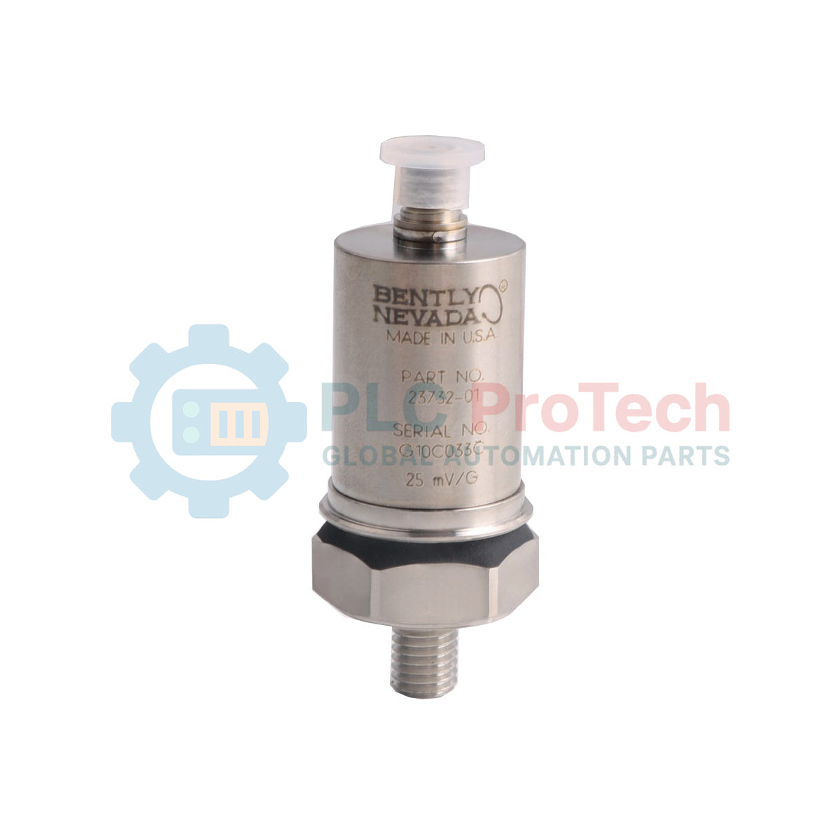
Designed for machinery protection and diagnostic monitoring, the Bently Nevada 23732-01 is a rugged, casing-mounted piezoelectric accelerometer optimized for high-frequency vibration measurement. It delivers a calibrated sensitivity of 25 mV/g and is engineered to withstand extreme industrial environments, providing reliable dynamic acceleration signals to monitoring systems such as the Bently Nevada 3500 series.
Key Features
-
Hermetically Sealed Case: Constructed from 316L stainless steel to resist highly corrosive and harsh process environments.
-
Broad Frequency Response: Capable of capturing vibration signatures from 10 Hz to 20 kHz.
-
High Shock Limit: Accommodates dynamic acceleration ranges up to 75 g peak.
-
Wide Temperature Range: Rated for stable operation across a temperature envelope from -29 degC to +121 degC.
Applications
- Casing vibration measurements on gas and steam turbines.
- Structural integrity and bearing housing monitoring in heavy-duty pumps, fans, and compressors.
- High-speed industrial gearboxes and large electric motors.
Technical Specifications
| Manufacturer |
Bently Nevada |
| Model Number |
23732-01 |
| Sensitivity |
25 mV/g (2.55 mV/m/s2) +/-5% |
| Acceleration Range |
75 g (735 m/s2) peak |
| Frequency Response |
10 Hz to 20 kHz (+/-3 dB); 30 Hz to 10 kHz (+/-5%) |
| Mounted Resonant Frequency |
30 kHz minimum |
| Operating & Storage Temperature |
-29 degC to +121 degC (-20 degF to +250 degF) |
| Relative Humidity |
To 95%, noncondensing |
| Hex Flats Size |
19.0 mm (0.75 in) |
| Case Material |
316L stainless steel |
| Weight |
60 g (2.1 oz) |
| Country of Origin |
United States of America (USA) |
| Shipping Weight (Calculated) |
1.0 kg |
Alternative Models & Compatibility
The 23732-01 is a legacy vibration transducer. When planning field replacements, note that newer installations typically deploy standard Bently Nevada accelerometers like the 200350 or 330400 series. Because the 23732-01 has a specific sensitivity profile of 25 mV/g, replacing it with a standard 100 mV/g sensor requires modification of the channel configuration scale factor inside the monitoring software to prevent severe calibration errors.
Application Pitfalls & Engineering Notes
Due to the lower sensitivity scale (25 mV/g vs typical 100 mV/g devices), ensure that all interconnecting cabling is highly shielded and routed away from high-voltage switchgear. A reduced signal-to-noise ratio can result if long cable runs are utilized without dedicated low-noise coaxial cabling. Additionally, verify that the structural mounting surface is completely flat and free from paint or debris to maintain accurate high-frequency coupling up to the sensor's 30 kHz resonant limit.
Commissioning & Wiring Tips
To prevent electrical noise and ground-loop interference from degrading the dynamic vibration waveform, the sensor cable shield must be grounded only at the monitor end. Ensure the sensor housing is physically isolated from local machine casing ground unless the receiving terminal module provides a dedicated isolated differential input stage.
Installation Guidelines
CRITICAL WARNING: De-energize and lock out all surrounding machinery before initiating mechanical installation. Verify that the machine casing temperature is cool enough to touch safely to prevent thermal shock to the sensor's internal piezoelectric crystal during mounting.
1
Prepare the mounting surface by spot-facing to a surface roughness of 0.8 micrometers (32 microinches) Ra. Ensure the mounting hole is tapped completely perpendicular to the surface.
2
Apply a light film of silicone grease or mounting lubricant to the base mating interface to optimize high-frequency acoustic coupling.
3
Thread the sensor into the mounting hole and torque to the nominal limit. Do not over-torque, as this can cause permanent mechanical bias or fracture the internal crystal structure.