Description
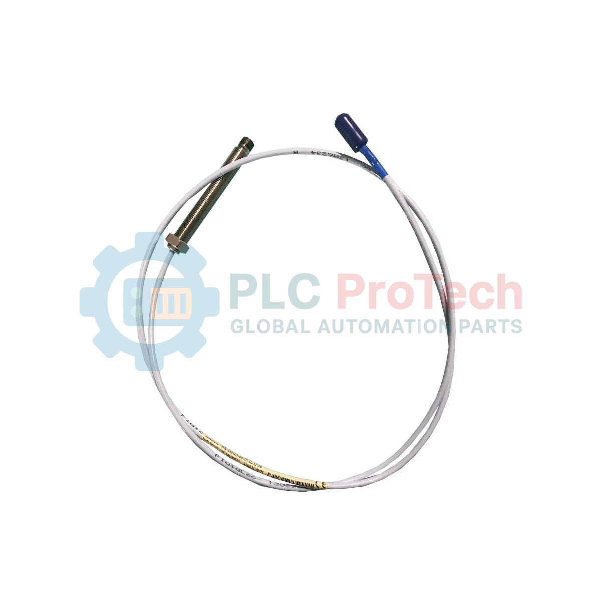
Engineered for critical machinery protection, the Bently Nevada 330101-00-10-05-02-CN delivers highly accurate, non-contacting vibration and displacement measurements on high-speed rotating shafts. This 3300 XL 8 mm proximity probe acts as a primary sensor transducer, translating physical shaft movement into dynamic electrical signals when paired with a compatible 3300 XL Proximitor Sensor. It features a rugged 3/8-24 UNF threaded body, an unthreaded length optimized for precise positioning, and an unarmored standard coaxial cable with a ClickLoc connector, making it ideal for standard industrial fluid-film bearing housings where mechanical shielding is not required.
Features
-
High-Performance Tip: 8 mm tip diameter constructed from high-durability polyphenylene sulfide (PPS) to resist harsh industrial environments.
-
Secure Coupling: Equipped with a miniature coaxial ClickLoc connector to resist vibration-induced signal disconnection.
-
Precision Case Design: Threaded 3/8-24 UNF casing ensures precise depth calibration during mechanical installation.
-
Unarmored Routing: Flexible standard coaxial cable layout for routing through tight internal machine passages and conduits.
-
Certified Hazardous Area Protection: CN suffix indicates country-specific explosion protection approvals for specialized territories.
Applications
- Steam and gas turbine shaft radial vibration monitoring.
- Thrust position and axial displacement tracking in centrifugal compressors.
- Mechanical runout measurements on electric generator rotors.
- Shaft orbit analysis on high-speed industrial gearboxes.
Ordering Information
| Option Code |
Parameter Description |
Configured Selection |
| 00 |
Unthreaded Length Option |
0.0 in (0 mm) |
| 10 |
Overall Case Length Option |
1.0 in (25.4 mm) |
| 05 |
Total Length Option |
0.5 meter (1.6 feet) |
| 02 |
Connector and Cable Type Option |
Miniature coaxial ClickLoc connector, standard cable |
| CN |
Agency Approval Option |
Country-specific certifications (CN Approvals) |
Technical Specifications
| Specification Parameter |
Value / Rating |
| Probe Tip Diameter |
8 mm |
| Thread Size |
3/8-24 UNF |
| Linear Range |
2.0 mm (80 mils) nominal |
| System Scale Factor |
7.87 V/mm (200 mV/mil) +/-5% (when system matched) |
| Operating Temperature Range |
-51 degC to +177 degC (-60 degF to +350 degF) |
| Connector System |
Coaxial ClickLoc connector (Gold-plated brass) |
| Minimum Bend Radius |
25.4 mm (1.0 in) |
| Manufacturer |
Bently Nevada (Baker Hughes) |
| Country of Origin |
United States of America |
| Shipping Weight (Calculated) |
2.0 kg |
| Packaging Dimensions (Calculated) |
220 mm x 180 mm x 60 mm |
Empirical Engineering Insights
To ensure correct system configuration and prevent measurement interference, verify the following field-validated engineering guidelines during the design and installation phase:
Alternative Models & Compatibility
This 0.5-meter probe is engineered for use with a 3300 XL Proximitor Sensor. It requires a specific extension cable (typically 4.5 meters or 8.5 meters) to achieve a matched system length of 5.0 meters or 9.0 meters. Intermixing 3300 XL components with older, non-XL 3300 series Proximitors or probes is physically possible but degrades the system's thermal stability and linearity curves.
Application Pitfalls & Engineering Notes
Maintain a clearance zone around the probe tip of at least 1.5 times the tip diameter (12 mm) from any adjacent metal structures to avoid side-loading (cross-talk) errors. Misaligning the probe face more than 5 degrees relative to the shaft surface target face degrades measurement linearity and changes the default 200 mV/mil calibration curve.
Commissioning & Wiring Tips
Clean the internal gold pin contacts of the coaxial ClickLoc connector with electronics-grade isopropyl alcohol before mating. Ensure the connector is fully inserted (indicated by an audible click) before tightening the knurled sleeve. Never use standard pliers directly on the connector bodies; always use specialized connector tools to avoid cracking the insulating layers.
Installation Guidelines
CRITICAL WARNING: De-energize all machinery and disconnect associated control room trip loops before mounting or adjusting the proximity probe. Ensure there is no residual shaft rotation or electrostatic charge buildup. Incorrect mechanical gaps can lead to physical probe tip contact with the rotating shaft, causing catastrophic machine damage and sensor destruction.
1
Thread the probe into the mounting bracket or bearing housing by hand until the tip lightly seats against the shaft target surface. Use extreme caution to avoid overtightening.
2
Back off the probe body to establish the target physical gap. For standard 3300 XL 8 mm systems, a gap of approximately 1.27 mm (50 mils), which corresponds to a DC voltage offset of -10.0 VDC on the Proximitor output, is standard.
3
Secure the locking nut to a maximum torque rating of 11.2 N-m (100 in-lb) to prevent the probe from backing out under severe operation vibration.