Description
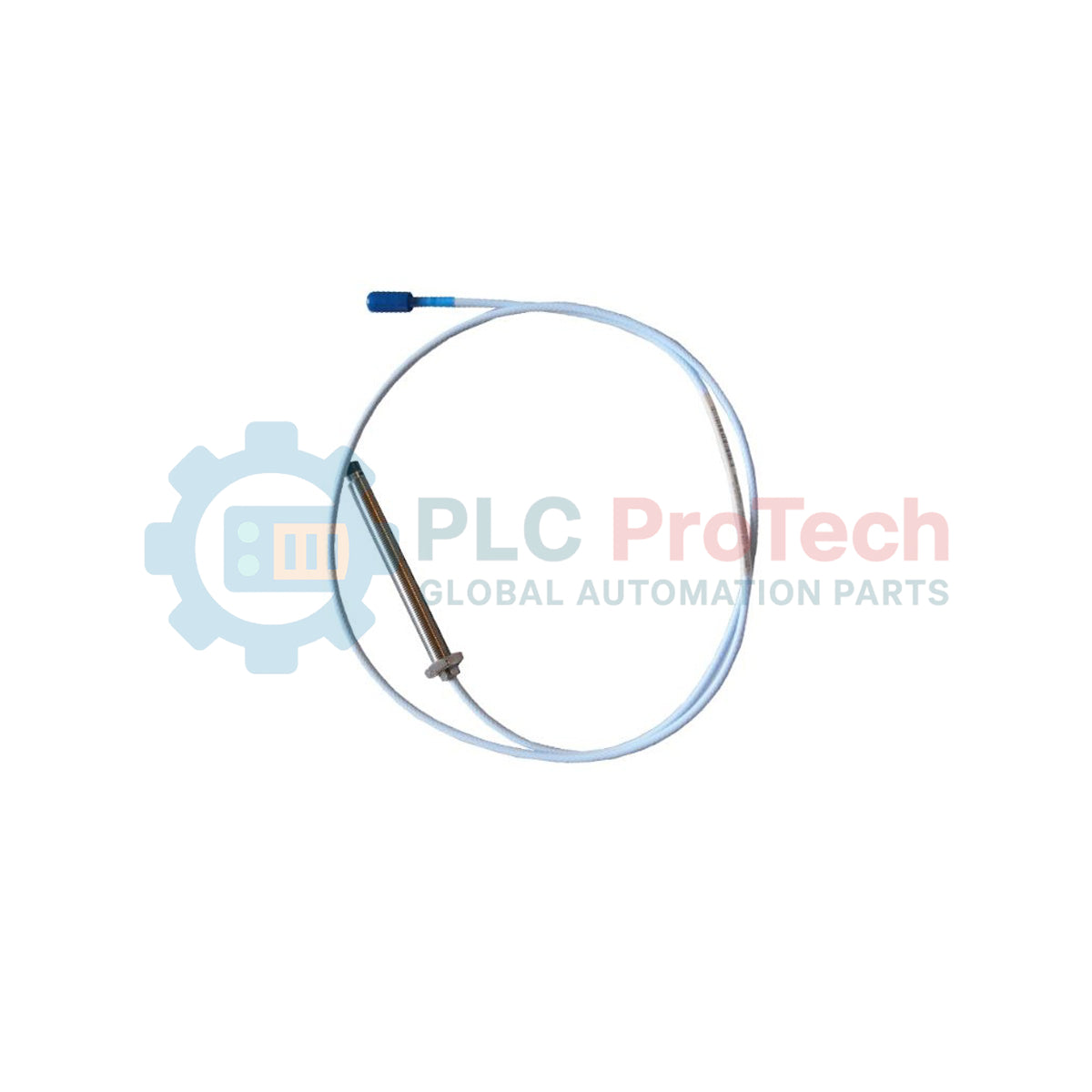
As a critical component in machinery protection systems, the Bently Nevada 330193-00-02-10-00 provides precise, non-contact displacement and vibration measurements under challenging thermal conditions. Engineered specifically for the 3300 XL 8 mm Extended Temperature Range (ETR) series, this proximity probe operates reliably in extreme high-temperature environments where standard sensors degrade. The system utilizes Eddy Current technology to monitor key mechanical parameters, including shaft vibration, radial position, and thrust position on critical rotating machinery.
Features
-
Extended Temperature Range (ETR): Built to endure higher temperature cycles without sacrificing signal stability or accuracy.
-
8 mm Tip Diameter: Optimized sensor head geometry for standard high-resolution proximity measurements.
-
Unthreaded Length Option (00): Configured with 0 mm unthreaded portion for specialized low-profile mounting profiles.
-
Overall Case Length Option (02): Features a compact 20 mm case length for integration into standard probe holders and housings.
-
Total Length Option (10): Equipped with a 1.0-metre (3.3 feet) integrated cable, ideal for direct coupling to connection boxes.
-
Gold-Plated Click-Loc Connectors: Corrosion-resistant termination ensuring high-signal integrity and vibration-resistant physical connections.
Applications
-
Steam and Gas Turbines: Monitoring shaft alignment and dynamic vibration levels in high-temperature zones.
-
Industrial Compressors: Radial and axial shaft displacement tracking on high-pressure casing designs.
-
Boiler Feed Pumps: Continuous health diagnostics in high thermal cycling and fluid-intensive operations.
-
Heavy-Duty Fans & Blowers: Real-time unbalance detection in power generation and petrochemical plants.
Ordering Information
| Option Code |
Configuration Parameter |
Value / Description |
| 00 |
Unthreaded Length |
0 mm |
| 02 |
Overall Case Length |
20 mm |
| 10 |
Total Length |
1.0 metre (3.3 feet) |
| 00 |
Agency Approval |
Not required |
Technical Specifications
| Manufacturer |
Bently Nevada |
| Part Number / SKU |
330193-00-02-10-00 |
| Product Series |
3300 XL 8 mm ETR |
| Tip Diameter |
8 mm |
| Case Thread Option |
Unthreaded (0 mm length) |
| Physical Case Length |
20 mm |
| Integrated Cable Length |
1.0 metre |
| Connector Style |
Miniature coaxial Click-Loc |
| Sensor Type |
Eddy Current Proximity Probe |
| Country of Origin |
USA |
| Shipping Weight (Calculated) |
1.5 kg (3.3 lbs) |
Connections and Interfaces
| Connector Element |
Type |
Functional Assignment / Requirements |
| Coaxial Center Pin |
Signal / High-Frequency RF |
Carries RF excitation signal from Proximitor Sensor and returns modulated voltage. |
| Coaxial Outer Shield |
Return Path / Common |
Establishes reference ground path. Must remain isolated from machine ground. |
| Click-Lock Joint |
Mechanical Coupler |
Locking mechanism. Requires connector protectors if exposed to fluids or oil. |
Empirical Engineering Insights
Alternative Models & Compatibility
The 330193-00-02-10-00 probe is strictly designed for integration within the 3300 XL 8 mm Extended Temperature Range system. It must be paired with an ETR extension cable and an ETR-compatible Proximitor Sensor. Mismatching this probe with standard, non-ETR 3300 XL extension cables or Proximitor Sensors introduces substantial linearity deviations and calibration shifts, rendering scale factors unreliable.
Application Pitfalls & Engineering Notes
When deploying the probe in high-temperature fluid boundaries, assure that the probe case thread interface is securely sealed. Since this unit features a 0 mm unthreaded portion, the case body is fully threaded up to the tip, demanding careful depth calculation within the bracket to prevent internal mechanical interference with the target shaft.
Commissioning & Wiring Tips
Always check the insulation resistance of the probe before and after installation to confirm that the sensor tip and the coaxial shield have not shorted directly to the machine casing. Connectors must be finger-tightened until the positive Click-Loc detent engages. Do not use pliers or heavy wrenches, as excessive torque will damage the internal coaxial termination.
Installation Guidelines
CRITICAL WARNING: Prior to probe installation or physical adjustment, fully de-energize and lock out all machinery. High-speed shaft rotation can cause catastrophic mechanical impact with the probe tip if clearance parameters are set incorrectly. Use calibrated non-magnetic feeler gauges or electric micrometer spindles to verify structural clearances before starting the system.
1
Calculate the required insertion depth based on the machine housing layout and the 20 mm overall case length.
2
Slowly thread the probe into the mounting bracket or sleeve, monitoring gap voltage using a digital multimeter connected to the Proximitor Sensor output.
3
Adjust the probe body until the output reads the nominal gap voltage specified by your monitoring system (typically -10.0 VDC for standard midrange calibration).
4
Secure the probe outer locknut to lock the assembly in place, then re-verify the static gap voltage to ensure the probe did not rotate during tightening.