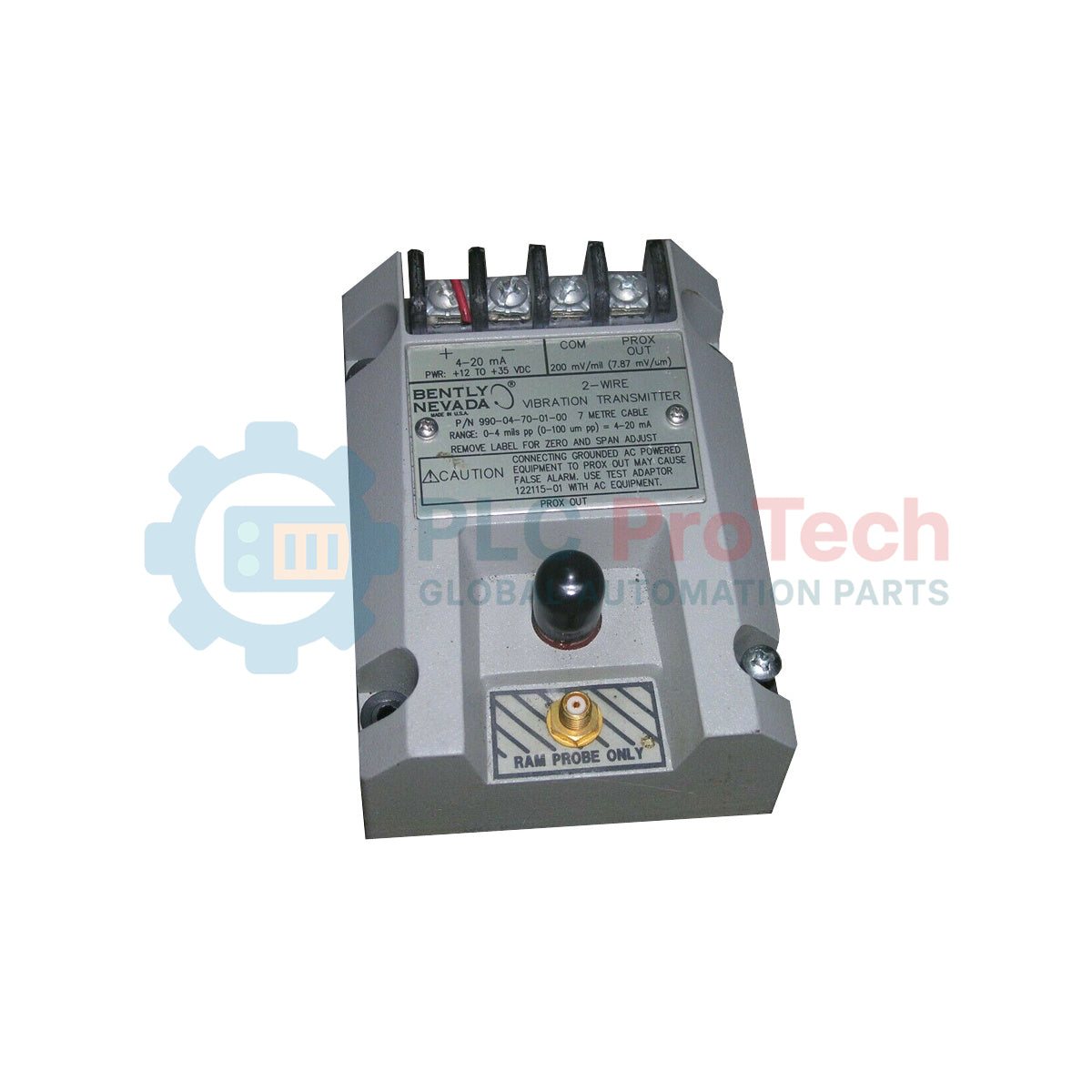
Description
Engineered for integration into PLC, DCS, and safety-instrumented machinery protection systems, the Bently Nevada 990-05-70-01-CN provides continuous proportional radial vibration monitoring via a robust 2-wire current loop. This transmitter conditions signals directly from a compatible proximity probe system to output a standard 4-20 mA analog signal, removing the need for dedicated monitor racks in the control architecture. The 990-05-70-01-CN is factory-calibrated for high-precision machinery diagnostics and features a 35 mm DIN rail mounting footprint for high-density control cabinet integration.
Features
-
2-Wire Loop Powered: Operates on standard 24 VDC loop power, reducing field wiring complexity and installation costs.
-
Continuous 4-20 mA Output: Delivers a stable analog signal proportional to the overall peak-to-peak radial vibration.
-
Integrated Prox Input: Interfaces directly with a 3300 NSv proximity transducer system.
-
DIN Rail Mounting: Factory fitted with 35 mm DIN rail clips for secure, space-efficient control room mounting.
-
Solid State Design: No moving parts or field adjustments required, ensuring long-term measurement stability.
Applications
- Centrifugal and reciprocating air/gas compressors
- Industrial draft fans, blowers, and exhausters
- High-speed process pumps and electric motors
- Small-scale steam turbines and gas expanders
Ordering Information
| SKU Segment |
Option Code |
Technical Meaning / Configuration |
| Full-scale Option |
05 |
0 to 5 mils pp (0 to 125 micrometers pp) |
| System Length Option |
70 |
7.0 meters (23.0 feet) |
| Mounting Option |
01 |
35 mm DIN rail clips installed |
| Agency Approval |
CN |
Country-specific approvals (China/CN zone compliance) |
Technical Specifications
| Manufacturer |
Bently Nevada (Baker Hughes) |
| Model Number |
990-05-70-01-CN |
| Input Sensor Compatibility |
3300 NSv Proximity Transducer System |
| Power Requirement |
12 to 35 VDC (Loop voltage at transmitter terminals) |
| Analog Output Signal |
4-20 mA (proportional to peak-to-peak vibration) |
| System Calibrated Length |
7.0 meters (including probe, extension cable, and transmitter) |
| Operating Temperature |
-35 to +85 Celsius |
| Country of Origin |
United States (USA) |
| Shipping Weight (Calculated) |
1.5 kg (3.3 lbs) |
| Package Dimensions (Calculated) |
15.2 cm x 12.7 cm x 10.2 cm (6.0 in x 5.0 in x 4.0 in) |
Connections and Interfaces
| Terminal / Connection |
Designation |
Functional Description |
| + / Loop |
Power positive |
+12 to +35 VDC Supply Line |
| - / Return |
Signal Output |
4-20 mA current output and return line |
| COM |
Sensor Common |
Common reference terminal for proximity probe return |
| PROX |
Probe Input |
Raw dynamic signal input from 3300 NSv probe |
| SHIELD |
Grounding Shield |
To prevent EMI noise; terminate at the instrument end only |
Empirical Engineering Insights
Alternative Models & Compatibility
This transmitter is strictly calibrated to be compatible with a 3300 NSv proximity probe configuration. It cannot be used with standard 3300 XL 8mm or 5mm probes because of different scale factors and sensor gap behaviors. Ensure that the total system length (probe plus extension cable) matches the 7.0-meter configuration specification exactly; mismatching system lengths will result in linearity and scaling calibration errors.
Application Pitfalls & Engineering Notes
Ensure that the 4-20 mA loop resistance is matched to the input voltage. If the voltage drops below 12 VDC at the transmitter terminal block during a maximum 20 mA loop excursion, the transmitter output will clamp, skewing high-vibration alarms. Avoid routing high-voltage motor power leads in parallel with the 990 transmitter cabling inside cable trays to prevent inductive noise injection.
Commissioning & Wiring Tips
During commissioning, verify the loop current with a high-accuracy digital multimeter in series with the return terminal. A static loop current of approximately 4.0 mA indicates a zero-vibration condition, whereas a current under 3.6 mA indicates a field sensor fault, probe disconnect, or open-circuit loop connection.
Installation Guidelines
CRITICAL WARNING: De-energize all associated loop power sources and instrument systems before performing mechanical mounting or field wiring terminations. Failure to isolate power lines can result in control loop short-circuits or accidental tripping of safety interlocks on critical rotating machinery.
1
Mount the 990-05-70-01-CN onto a rigid 35 mm DIN rail inside a dry, low-vibration enclosure to minimize thermal drift and atmospheric contamination.
2
Connect the 3300 NSv proximity probe coaxial connector or cable to the designated PROX and COM terminal blocks using correct insulation and torque limits.
3
Route shielded, twisted-pair field cables to the + and - loop terminals, and connect the shield wire to the DCS or PLC instrumentation ground terminal only.
4
Apply 24 VDC loop power and verify loop current baseline performance at 4 mA with the machine in a shut-down, vibration-free state.