Description
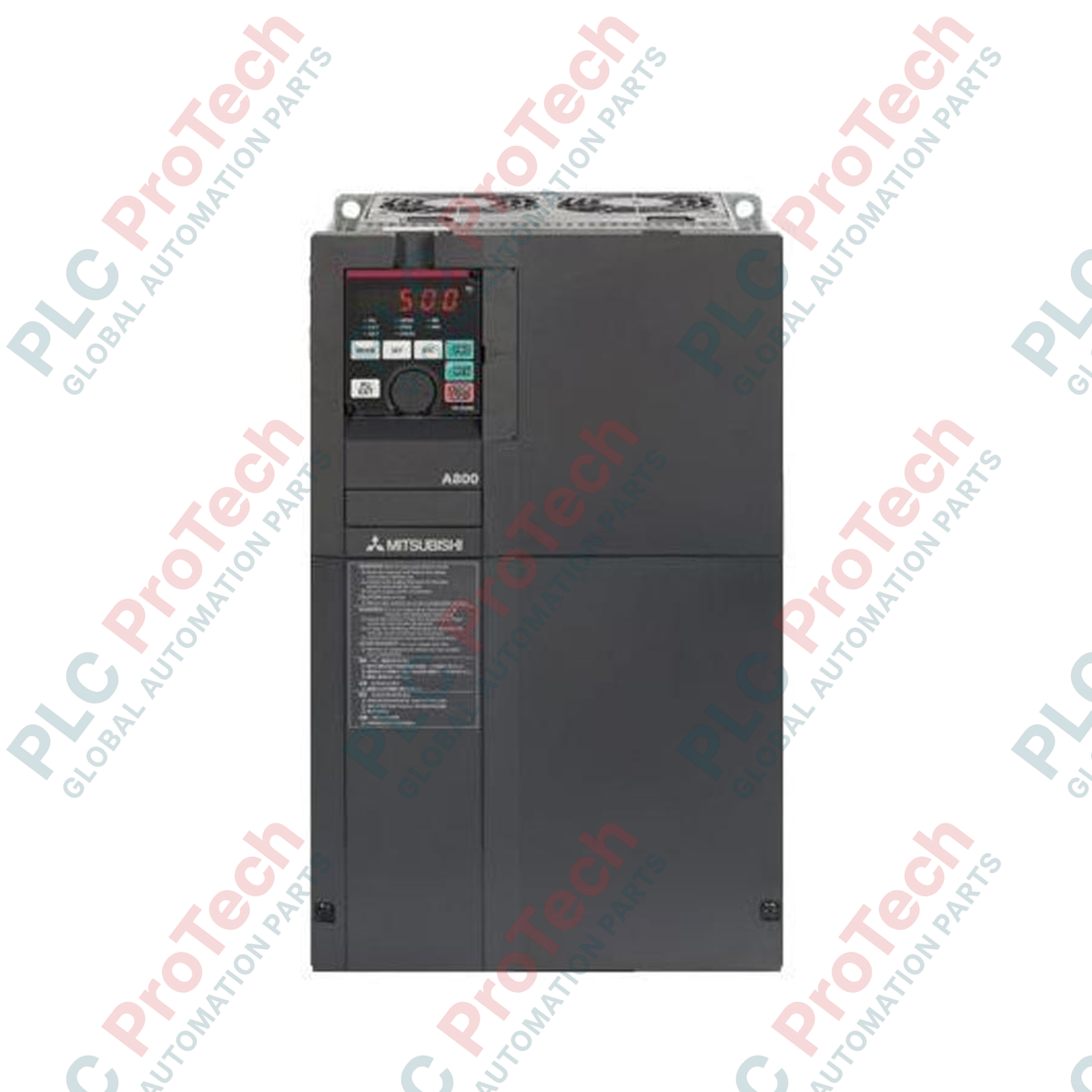
Designed to meet the rigorous demands of heavy industrial motor control, the Mitsubishi Electric FR-A840-01160-2-60 is a high-performance variable frequency drive (VFD) from the flagship FR-A800 series. This 400V class inverter delivers precise control with a Super Light Duty (SLD) rated current of 116A, making it ideal for high-capacity fan, pump, and machinery installations. Engineered with a specialized varnished circuit board coating (-60 specification), it provides reliable defense against humidity and dust in demanding environments. Its IP00 open-type physical structure is optimized for integration into centralized control panels, leveraging forced air cooling to maintain thermal efficiency under continuous operation.
Features
-
Varnished Circuit Boards: Enhanced conformal coating (-60 spec) safeguards control and power electronics from atmospheric contamination without plated conductors.
-
High Current Capacity: Operates at 116A under Super Light Duty (SLD) rating, supporting demanding heavy-duty continuous operations.
-
Robust Voltage Tolerances: Designed for standard three-phase 380V to 500V AC power systems, with a reliable fluctuation tolerance of 323V to 550V AC.
-
Panel-Optimized Design: Open-type IP00 rating allows efficient, space-saving panel installations with integrated forced-air cooling.
-
High-Precision Control: Part of the advanced FR-A800 family, supporting real sensorless vector control and vector control options.
Applications
-
Industrial Ventilation Systems: High-volume fan arrays, blowers, and clean-room exhaust systems requiring continuous speed modulation.
-
Water and Wastewater Management: Centrifugal pumps, booster stations, and fluid processing plants.
-
Heavy Machinery Control: Extruders, large conveyor lines, and material handling systems requiring steady-state torque control.
Technical Specifications
| Parameter |
Specification Value |
| Manufacturer |
Mitsubishi Electric |
| Model Number |
FR-A840-01160-2-60 |
| Series |
FR-A800 Inverter Series |
| Voltage Class |
400V Class |
| Rated Input AC Voltage |
Three-phase 380V to 500V AC, 50Hz/60Hz |
| Permissible AC Voltage Fluctuation |
323V to 550V AC, 50Hz/60Hz |
| Permissible Frequency Fluctuation |
+/-5% |
| SLD Rated Current |
116 A |
| Control/Structure Type |
Standard Model (-2 = CA Type) |
| Protective Structure |
Open Type (IP00) |
| Cooling Method |
Forced Air Cooling |
| Circuit Board Coating |
Varnished Conformal Coating (-60 specification) |
| Plated Conductor |
None |
| Product Weight |
41 kg (90.4 lbs) |
| Shipping Weight (Calculated) |
43 kg (94.8 lbs) |
Connections and Interfaces
| Terminal Block / Interface |
Functional Allocation |
| R/L1, S/L2, T/L3 |
Three-Phase AC Mains Power Input Terminals |
| U, V, W |
Three-Phase Variable Frequency AC Output to Motor |
| P/+, N/- |
DC Link Connection Terminals for Brake Unit or Shared DC Bus |
| PE |
Protective Earth / Chassis Ground Terminal |
| Control Terminals |
Dedicated I/O, Analog inputs (0-10V, 4-20mA), and multi-function relay outputs |
Empirical Engineering Insights
Alternative Models & Compatibility
When migrating legacy systems from the FR-A700 series, the FR-A800 series provides backward parameters conversion. Parameter configurations can be imported using Mitsubishi’s FR Configurator2 software. Note that control terminal assignments are closely matched, but manual confirmation of safety-stop circuit allocations is required because of the safety standards implementation in the FR-A800 architecture.
Application Pitfalls & Engineering Notes
Because this VFD has a 41 kg weight footprint and relies on high-velocity forced air cooling, panel builders must ensure adequate airflow. Sealed enclosures require active heat exchangers or air conditioning units to handle the thermal load generated by the drive under continuous 116A SLD load conditions. Maintaining a minimum clearance of 100 mm above and below the cooling fans is necessary to prevent thermal shutdown events.
Commissioning & Wiring Tips
During initial power-up, verify that parameter 9 (electronic thermal O/L relay) matches your specific motor's nameplate data. Ensure all control-signal cables (such as 0-10V analog speed inputs) are routed in dedicated, shielded conduits distinct from high-power input/output cabling to eliminate high-frequency electromagnetic coupling.
Installation Guidelines
CRITICAL WARNING: Before commencing any installation or maintenance procedures, ensure all AC power sources feeding the R/L1, S/L2, and T/L3 terminals are physically locked out and tagged out. After power-off, wait a minimum of 10 minutes to allow the internal DC bus link capacitors to discharge completely. Verify that the voltage between terminals P/+ and N/- is 0V using a calibrated digital multimeter before handling terminals.
1
Mount the VFD vertically on a rigid, flat, heat-resistant surface inside the electrical enclosure to maximize convective air currents.
2
Connect the dedicated ground terminal (PE) directly to the system grounding plate using a low-impedance copper conductor.
3
Perform input power and motor terminal connections using calibrated torque tools, ensuring correct phase sequence on U, V, and W outputs.