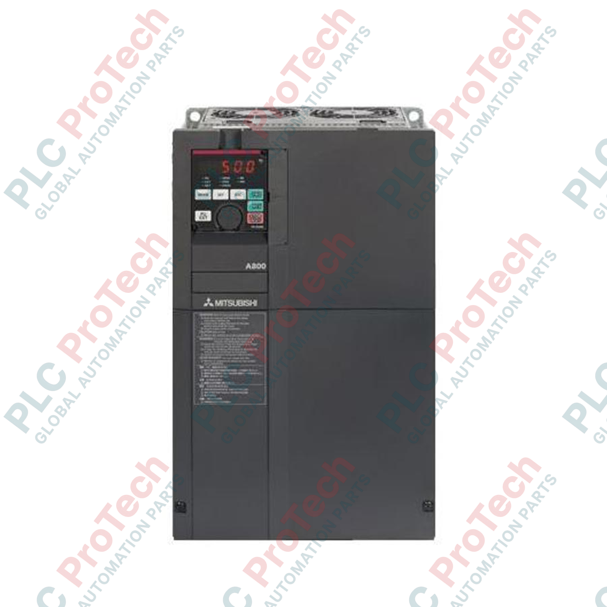
Description
Engineered for highly demanding industrial automation applications, the Mitsubishi Electric FR-A840-03610-2-60 variable frequency drive provides advanced speed, torque, and vector control as part of the premier FR-A800 Series. This high-capacity, three-phase inverter is configured as a standard model featuring specialized circuit board conformal coating (Class 3C2) for superior environmental resistance in harsh operating conditions, though it does not include plated conductors. Utilizing an adaptable multi-rating architecture, it optimizes performance across various duty cycles, ensuring robust motor control and minimized downtime in complex system integrations.
Features
-
Conformal Coating (3C2): Enhanced defense against dust, humidity, and corrosive atmospheric gases.
-
Multi-Rating Flexibility: Four built-in overload ratings (SLD, LD, ND, HD) to match specific load characteristics.
-
Advanced Vector Control: Supports Real Sensorless Vector Control (RSV) and PM sensorless vector control for precise torque performance.
-
Energy-Saving Technology: Optimum excitation control maximizes motor efficiency and minimizes power consumption.
-
Comprehensive Safety Functions: Features integrated safe torque off (STO) safety inputs complying with global safety standards.
Applications
- High-capacity water and wastewater pumping networks.
- Industrial fan systems and air handling units with variable torque demands.
- Extruders, mixers, and heavy-duty conveyor systems.
- Hoisting, crane, and material handling systems requiring high starting torque.
Technical Specifications
| Parameter |
Specification Value |
| Manufacturer |
Mitsubishi Electric |
| Model Code |
FR-A840-03610-2-60 |
| Series |
FR-A800 Series |
| Voltage Class |
400V Class (Three-Phase 380V to 500V AC, 50/60Hz) |
| SLD Rated Current |
361 A (Super Light Duty) |
| LD Rated Current |
310 A (Light Duty) |
| ND Rated Current |
260 A (Normal Duty) |
| HD Rated Current |
216 A (Heavy Duty) |
| Structure/Functionality |
Standard Model (Type 0) |
| Board Coating |
With Conformal Coating (IEC 60721-3-3 Class 3C2) |
| Plated Conductor |
Without Plating |
| Cooling Method |
Forced Air Cooling |
| Operating Temperature |
-10 degC to +50 degC (non-freezing, matching rated load capacity) |
| Shipping Weight (Calculated) |
80.0 kg |
Connections and Interfaces
| Terminal Group |
Description & Assignment |
| R/L1, S/L2, T/L3 |
Three-phase AC power input supply terminals |
| U, V, W |
Three-phase AC output connections to the motor |
| STF / STR |
Forward Start / Reverse Start digital input control commands |
| SD / PC |
Common terminal for contact input / External transistor power source (24VDC) |
| A1, B1, C1 |
Relay output terminals (Fault output indicator) |
Empirical Engineering Insights
Alternative Models & Compatibility
When replacing an older legacy series inverter (such as the FR-A740 series), keep in mind that control terminal configurations are substantially compatible, but terminal block positioning and dimensions may vary. The "-2-60" suffix indicates this drive features specialized 3C2 conformal board coating; it serves as a direct, rugged upgrade to standard uncoated variants (such as the base FR-A840-03610) without modifying any application parameters or cabinet configurations.
Application Pitfalls & Engineering Notes
At the 361A Super Light Duty rating, the drive is highly sensitive to input supply phase imbalances. Ensure line-side voltage deviation does not exceed 3% between phases to prevent localized overheating in the input rectifier bridge. Because this model does not feature plated conductors, avoid deploying this specific configuration in environments with active exposure to direct hydrogen sulfide gas unless the main enclosure is sealed to an IP54 or higher standard and utilizes external heat exchanges.
Commissioning & Wiring Tips
Verify the position of the slide switch on the control terminal circuit board to correctly select between SINK (NPN) and SOURCE (PNP) logic states before powering up the drive's control circuitry. Improper selection may lead to internal control board damage or unexpected behavior of digital inputs. Keep control signal wiring separated from high-power motor cabling by at least 30 cm, crossing them only at right angles to minimize electro-magnetic interference (EMI).
Installation Guidelines
CRITICAL WARNING: HIGH VOLTAGE HAZARD
Isolate all electrical power sources before performing mechanical installation or internal wiring. Verify that the DC bus charge indicator LED on the front cover is completely unlit, and measure the voltage across terminal blocks P/+ and N/- using a calibrated voltmeter to ensure it is below 45V DC. Failure to follow discharge protocol can result in catastrophic shock or fatal injury.
1
Mount the inverter vertically to a rigid, non-flammable vertical support panel. Ensure at least 10 cm of clear vertical space above and below the unit to allow free airflow from the forced cooling fans.
2
Connect the dedicated ground terminal to the main system grounding point using heavy gauge wire conforming to local electrical codes to mitigate high-frequency leakage currents.
3
Wire the main power input terminals (R/L1, S/L2, T/L3) and the motor output terminals (U, V, W) using appropriately sized cable lugs torqued precisely to the manufacturer's specified tightening values.