Description
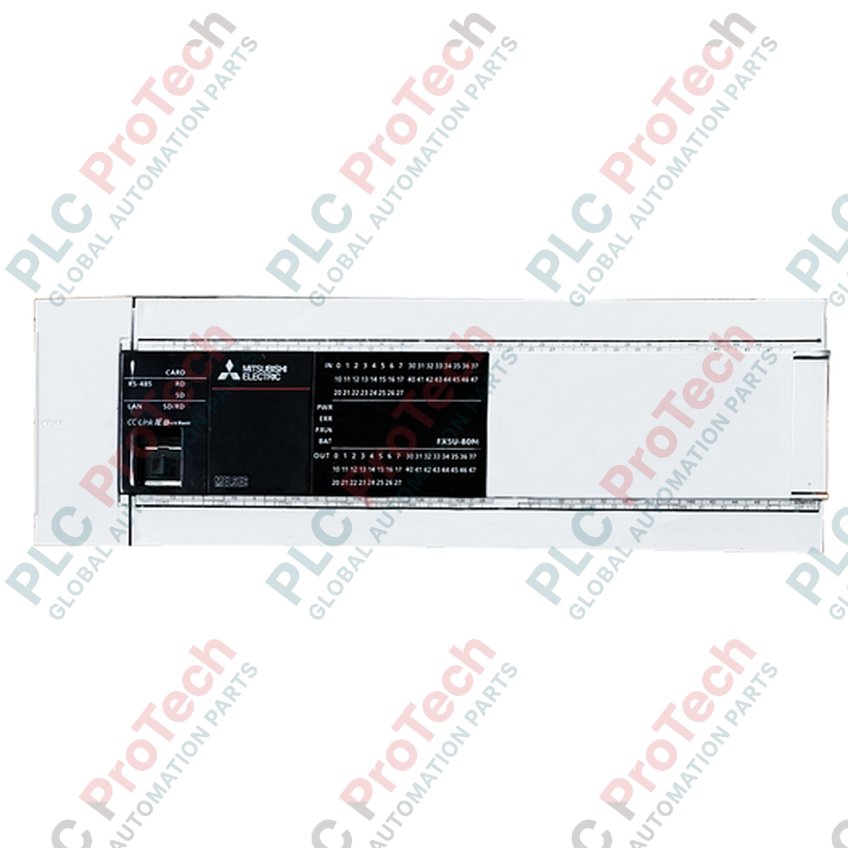
Designed as a high-performance control engine for the MELSEC iQ-F platform, the Mitsubishi Electric FX5U-80MT/ESS programmable logic controller offers exceptional processing speeds and integrated industrial functionalities. This module features 80 built-in I/O channels (comprising 40 source/sink 24V DC inputs and 40 source-type transistor outputs) designed to coordinate complex automation tasks. The controller incorporates native analog inputs and outputs, a dedicated RS-485 port, and an Ethernet interface to support diverse industrial communication requirements directly from the base unit without requiring additional expansion cards.
Key Features
-
High-Speed System Bus: Facilitates ultra-fast communication with extension modules, minimizing signal propagation delay.
-
Integrated Analog I/O: Built-in 2-channel analog input (0 to 10 V DC) and 1-channel analog output (0 to 10 V DC) for direct sensor and actuator interfacing.
-
Advanced Positioning: Supports built-in 4-axis positioning control with dedicated high-speed counter inputs.
-
Industrial Communications: Native RJ45 Ethernet port and screw-terminal RS-485 connection for seamless integration into factory networks.
-
SD Card Slot: Onboard memory card slot for program logging, firmware updates, and recipe management.
Applications
- High-speed packaging and sorting machinery.
- Multi-axis pick-and-place gantry systems.
- Water treatment control panels with analog flow/pressure monitoring.
- Conveyor control and material handling distribution systems.
Technical Specifications
| Parameter |
Specification Value |
| Manufacturer |
Mitsubishi Electric |
| Model Family |
MELSEC iQ-F Series (FX5U) |
| Supply Voltage |
100 to 240 V AC (+10% / -15%), 50/60 Hz |
| Power Consumption |
45 W |
| Total Built-in I/O Points |
80 points (40 inputs, 40 outputs) |
| Input Specifications |
24 V DC, 5.3 mA (X0 to X17) / 4.0 mA (X20 and later), Sink or Source configurable |
| Output Specifications |
Transistor (Source type), 5 to 30 V DC, 0.5 A per point |
| Built-in Analog Inputs |
2 channels (0 to 10 V DC, input resistance 115 kOhms, 12-bit resolution) |
| Built-in Analog Output |
1 channel (0 to 10 V DC, load resistance 2 kOhms to 1 MOhms, 12-bit resolution) |
| Built-in Communication Ports |
1x RJ45 Ethernet (100Base-TX/10Base-T), 1x RS-485 (terminal block) |
| Operating Temperature |
0 to 55 degC (32 to 131 degF) |
| Country of Origin |
Japan |
| Shipping Weight (Calculated) |
1.2 kg (Net), 1.45 kg (Packaged) |
| Package Dimensions (Calculated) |
305 mm x 110 mm x 100 mm |
Connections and Interfaces
| Terminal Block Section |
Signal / Pin Assignment |
Wiring Description |
| Power Terminals |
L, N, PE |
100 to 240 V AC supply line, neutral, and physical protective earth. |
| Input Terminals |
S/S, X0 to X47 |
Configure S/S terminal for sink (connected to 24V) or source (connected to 0V) operations. |
| Output Terminals |
+V0 to +V4, Y0 to Y47 |
Source transistor outputs. External load connected between Y terminal and 0V line. |
| Analog Terminals |
V+, V-, CH1, CH2 |
Voltage inputs/outputs (0 to 10 V DC) for native processing. Shielded cables required. |
Empirical Engineering Insights
Alternative Models & Compatibility
This controller serves as the direct evolutionary upgrade path for legacy FX3U systems. Migration from FX3U to FX5U requires software conversion via GX Works3. Be aware that the I/O terminal block alignment and physical footprint differ from older designs; ensure layout diagrams are updated to accommodate the compact housing of the FX5U model.
Application Pitfalls & Engineering Notes
When utilizing all 40 transistor outputs under continuous maximum switching states in a fully populated cabinet, local thermal limits can be reached. Ensure the enclosure provides adequate passive ventilation or active cooling to maintain ambient temperatures below 55 degC. To prevent inductive kickback from damage, external freewheeling diodes must be mounted parallel to inductive DC loads (solenoids, contactor coils) connected to Y0-Y47.
Commissioning & Wiring Tips
To configure the sink/source digital inputs, the S/S terminal must be explicitly jumpered. Wiring S/S to 24V establishes a sink input loop, whereas wiring S/S to 0V establishes a source loop. Do not leave the S/S terminal floating. For RS-485 communications, enable the terminal resistor (110 Ohm or 330 Ohm) via the built-in switch at physical bus boundaries to prevent data reflection and signal degradation.
Installation Guidelines
CRITICAL WARNING: Disconnect all primary power before mounting, terminating, or modifying wiring on the PLC. Failure to isolate power can result in permanent equipment damage, arc flash, or personal injury. Ensure the auxiliary 24 V DC power supply is monitored and protected by an external fast-acting fuse.
1
Mount the PLC onto a standard 35mm DIN rail inside a protective, IP54-rated or better cabinet to avoid contamination from conductive dust or moisture.
2
Ensure the physical ground terminal (PE) is connected directly to the main cabinet ground bus using a short, low-impedance conductor (minimum 2 mm² copper wire).
3
Isolate high-voltage AC lines from low-voltage DC and communication pathways in separate wire ducts to avoid EMI coupling.