Description
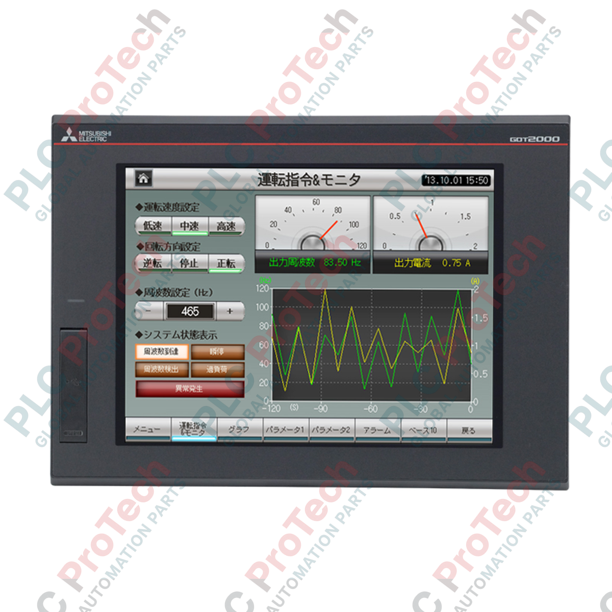
Engineered to deliver high-resolution process visualization and intuitive system control, the Mitsubishi Electric GT2710-STBA serves as a high-performance operator interface within complex automation architectures. Featuring a 10.4-inch SVGA TFT color display, this Human-Machine Interface (HMI) integrates capacitive multi-touch gesture capability, allowing operators to execute pinch-to-zoom, swipe, and dual-hand control actions directly on the factory floor. Equipped with an industrial-grade AC power supply, it is designed for installation in electrical control cabinets operating under rugged environmental and electrical conditions.
Key Features
-
Multi-Touch Capability: Supports standard gesture operations to prevent accidental inputs and streamline complex panel interactions.
-
TFT Color Screen: Displays process parameters with high-contrast SVGA resolution (800 x 600 pixels) for crisp text and detailed graphic screens.
-
Wide Input Voltage Range: Operates reliably on alternating current from 100 to 240 VAC with tolerance configurations of +10% to -15%.
-
Physical Resilience: Built with a black frame and certified to withstand mechanical impacts up to 147 m/s2 (15G) across three orthogonal axes.
-
Robust Insulating Barrier: Withstands test voltages of up to 1500 VAC for 1 minute between the live power terminals and the chassis ground.
Applications
- Automotive assembly plants and robotic manufacturing lines.
- Pumping, filtration, and dosing systems in water and wastewater facilities.
- Packaging, sorting, and material handling systems requiring rapid manual overrides.
- Chemical processing and environmental monitoring control panels.
Technical Specifications
| Parameter |
Value / Specification |
| Manufacturer |
Mitsubishi Electric |
| Model Number |
GT2710-STBA |
| Series |
GOT2000 Series (GT27) |
| Display Size & Type |
10.4-inch SVGA TFT Color Display |
| Resolution |
800 x 600 Pixels |
| Input Power Supply Voltage |
100 to 240 VAC (+10%, -15%), 50/60 Hz |
| Maximum Power Load |
41 W or less |
| Power Consumption (Standalone) |
17 W (10 W with backlight disabled) |
| Inrush Current |
60 A or less (duration 2 ms, 25 degC ambient) |
| Operating Temperature (Horizontal) |
0 to 55 degC |
| Operating Temperature (Vertical) |
0 to 50 degC |
| Operating Humidity |
10% to 90% RH (non-condensing) |
| Permissible Instantaneous Failure Time |
Within 20 ms (at 100 VAC or above) |
| Insulation Resistance |
10 MOhm or higher (measured at 500 VDC) |
| Physical Dimensions (W x H x D) |
303 mm x 218 mm x 25 mm |
| Weight (Excluding Brackets) |
2.1 kg |
| Shipping Weight |
8.0 kg |
Empirical Engineering Insights
Alternative Models & Compatibility
The unit serves as a functional replacement path for older GT1675-VNBA and GT1675-VNBA series operator terminals. When migrating projects via GT Works3, confirm that system fonts, touch-key touch zones, and direct communication settings are compiled for the GOT2000 hardware layer to ensure screen scaling and touch responsiveness operate as designed.
Application Pitfalls & Engineering Notes
Note the physical mounting orientation thermal penalty. A vertical configuration reduces convective heat dissipation capacity, reducing the allowable safe ambient envelope limit from 55 degC to 50 degC. Ensure sufficient enclosure volume is reserved to prevent hotspot build-up, especially when mounting direct-drive contactors or high-heat variable speed drives directly beneath the terminal cut-out.
Commissioning & Wiring Tips
Use separate physical runs for the AC feed and any signal cabling to prevent inductive coupling. The screw terminal blocks (M3 type) must be torqued to a range of 0.5 to 0.8 N.m using insulated tools. Always connect the functional ground terminal directly to a dedicated Class D low-impedance ground point (less than 100 Ohms) to minimize electromagnetic noise from local power electronics.
Installation Guidelines
CRITICAL SAFETY WARNING
Ensure all main, auxiliary, and control power feeds to the enclosure are completely de-energized, locked out, and tagged out prior to making physical contact with the terminals. Confirm the absence of hazardous residual voltage with a calibrated test instrument before initiating wiring steps.
1
Prepare the panel door cutout according to the installation manual template dimensions. Ensure the structural plate is level, rigid, and clear of rough burrs or metal chips.
2
Verify that the waterproof gasket is correctly seated around the back panel's perimeter. Insert the screen from the front panel into the prepared cabinet cutout.
3
Attach the mounting brackets from the rear and tighten the mounting screws evenly to secure the gasket seal and prevent mechanical distortion of the HMI bezel.
4
Strip incoming 100-240 VAC wire conductors to size (0.75 to 2 mm2). Crimp clean insulated spade or ring terminals, connect them to the M3 screw blocks, and torque securely to standard specs.