Description
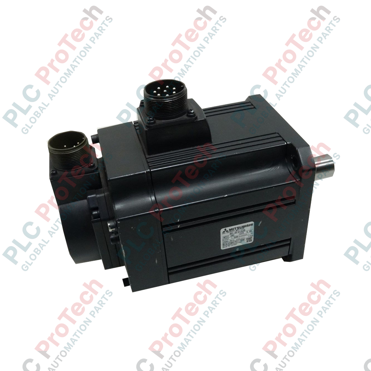
Designed for high-precision industrial motion control, the Mitsubishi Electric HC-SFS152B AC Servo Motor delivers robust dynamic performance within the MELSERVO system architecture. Operating at a 1.5 kW rated output and a 2000 r/min rated speed, this medium-inertia motor is engineered for applications requiring high-stability load matching and reliable speed control. Featuring an integrated electromagnetic brake for hold-on-power-off safety, the unit is constructed with a totally-enclosed, self-cooled IP65 housing (excluding the shaft throughput) to withstand challenging industrial environments where dust and liquid ingress are prevalent.
Key Features
-
Integrated Electromagnetic Brake: 24V DC holding brake ensures position retention during emergency stops or power loss.
-
Class F Insulation: High thermal threshold rating ensures winding protection during heavy cyclic duties.
-
IP65 Protection: Dust-tight and moisture-resistant construction suitable for demanding manufacturing bays.
-
Factory-Installed Oil Seal: Prevents lubricant migration when direct-coupling to gearboxes or actuators.
-
Optimized Inertia Design: Medium-to-high inertia characteristics reduce resonance and ease mechanical tuning.
Industrial Applications
-
Packaging Machinery: Multi-axis vertical form-fill-seal and high-speed indexing systems.
-
Material Handling: Gantry crane axes, transfer shuttles, and precise positioning conveyors.
-
CNC Machining: Dedicated feed axes and rotary axes on metal-cutting and woodworking stations.
-
Automated Assembly: High-payload robotic pick-and-place arms and automated press feeds.
Technical Specifications
| Specification Parameter |
Value / Details |
| Manufacturer |
Mitsubishi Electric |
| Model Code |
HC-SFS152B |
| Product Series |
MELSERVO HC-SFS Series |
| Rated Output Power |
1.5 kW |
| Rated Speed |
2000 r/min |
| Electromagnetic Brake |
Yes (24V DC holding brake, B-Type suffix) |
| Protection Structure |
IP65 (excluding shaft passage) |
| Cooling System |
Totally-enclosed, self-cooled |
| Insulation Class |
Class F |
| Standard Accessories |
Integrated oil seal |
| Shipping Weight |
13.0 kg |
Connections and Interfaces
| Connector/Terminal |
Function / Pin Assignment |
| Motor Power Connector |
U, V, W, and Protective Earth (PE) connections for amplifier drive output. |
| Brake Terminals |
24V DC excitation input pins. Non-polarized connection to release holding brake. |
| Encoder Connector |
Multi-pin absolute/incremental feedback interface linking directly to servo driver. |
Empirical Engineering Insights
Alternative Models & Compatibility
This unit is primarily paired with the MR-J2S-100A or MR-J2S-100B series servo amplifiers. When replacing older HC-SF models, verify overall length changes due to the integrated electromagnetic brake unit ("B" designation). Motor cables and encoder lead configurations are not directly interchangeable with MR-J3 series equivalents without specific conversion connectors.
Application Pitfalls & Engineering Notes
The pre-installed oil seal should never be run dry. If the motor is mounted standalone without an adjacent fluid-filled gearbox interface, ensure a light film of synthetic grease is applied to the lip to prevent frictional overheating and premature seal deterioration. Operating temperature should be maintained below 40 degrees Celsius ambient to preserve winding lifespan under heavy duty cycles.
Commissioning & Wiring Tips
Always routing encoder cables separate from high-power phase cables is highly critical to eliminate signal interference issues. Ground the motor chassis frame firmly to the electrical enclosure backplate. When configuring the amplifier, program a brake-release delay time (typically 50–100ms) to ensure the motor is excited and torque is applied prior to releasing the physical electromagnetic brake shoe.
Installation Guidelines
CRITICAL WARNING
Isolate and lock out all upstream electrical power supplies before performing installation, wiring, or inspection. Ensure the holding brake system is physically secured and cannot slide or drop loads before releasing motor shaft couplings.
1
Mount the motor on a flat, low-vibration metallic surface to facilitate natural heat dissipation.
2
Ensure precise alignment of the coupling mechanism to prevent high radial or axial thrust forces on the bearing set.
3
Connect the power, encoder, and auxiliary brake lines using double-shielded industrial cables, ensuring IP65-rated gland seals are tight.