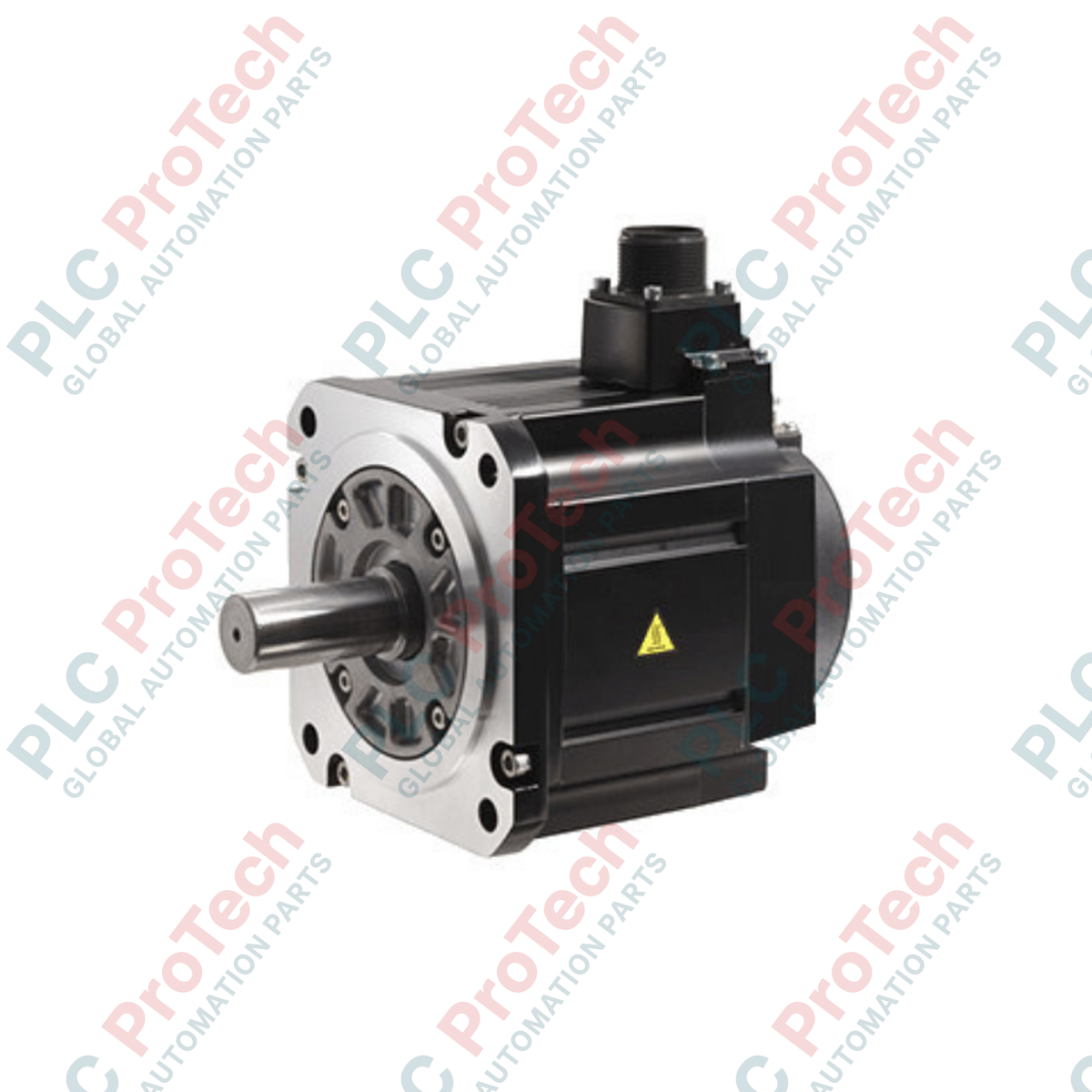
Description
Delivering precise dynamic response and high positioning accuracy within demanding motion architectures, the Mitsubishi Electric HG-SN152BJ-S100 is an AC servo motor engineered for high-inertia applications. This unit features a rated output of 1.5 kW and operates at a base speed of 2000 r/min, utilizing a totally enclosed, naturally cooled housing designed to survive challenging environmental exposures. Standard mechanical integration features include an integrated electromagnetic safety brake and a pre-installed oil seal to maintain mechanical integrity under persistent liquid and lubricant splashes.
Key Technical Features
-
Holding Brake Integration: Equipped with an internal electromagnetic safety brake designed to lock load positioning upon de-energization or emergency stop triggers.
-
Robust Environmental Sealing: Featuring a highly resilient IP67 rating with a pre-configured oil seal protection system to prevent oil and moisture ingress.
-
High Torque Performance: Delivers continuous rated torque of 7.16 Nm, suitable for material handling and indexing systems.
-
High Shock Resistance: Rated for a 24.5 m/s2 vibration threshold in transverse axes to assure stability during high acceleration ramps.
Industrial Applications
-
Multi-Axis CNC Tooling: High precision rotational axis drive and indexing axes.
-
Automated Packaging Systems: High speed pick-and-place lines, sealing bars, and carton folding machines.
-
Material Handling & Gantry Units: XY axis gantries, automated storage and retrieval systems (ASRS).
Technical Specifications
| Specification Parameter |
Value / Detail |
| Manufacturer |
Mitsubishi Electric |
| Model Identifier |
HG-SN152BJ-S100 |
| Motor Series |
HG-SN Series |
| Rated Output Power |
1.5 kW |
| Rated Torque |
7.16 Nm |
| Rated Speed |
2000 r/min |
| Maximum Speed |
3000 r/min |
| Instantaneous Permissible Speed |
3450 r/min |
| Rated Current |
9.4 A |
| Maximum Current |
29 A |
| Electromagnetic Safety Brake |
Yes (Spring-actuated holding type) |
| Oil Seal Configuration |
Installed |
| IP Rating |
IP67 (excluding shaft-through portion) |
| Insulation Class |
Class 155 (F) |
| Vibration Resistance |
X, Y: 24.5 m/s2 |
| Ambient Operating Temperature |
0 degC to 40 degC (non-freezing) |
| Net Weight |
9.3 kg |
| Shipping Weight |
10.5 kg |
Alternative Models & Compatibility
The HG-SN152BJ-S100 is designed directly for operation with the MELSERVO-JE / MR-JE-100B or MR-JE-100A amplifier series, as well as the high-tier MR-J4 series. When transitioning legacy platforms, this unit is a modern functional alternative to older HF-SP152B models. Always ensure configuration software is updated to the latest database version (MR Configurator2) to properly download current parameters and avoid auto-configuration errors.
Application Pitfalls & Engineering Notes
The integrated electromagnet safety brake is strictly a holding brake. It must not be deployed for dynamic deceleration or rotational speed control, as doing so will cause rapid frictional degradation, localized thermal overloading, and mechanical failure. Ensure that the external drive profile triggers the holding brake only after the motor shaft has reached complete zero-speed status. Additionally, when using the pre-installed oil seal, ensure that the oil level on the gear flange does not exceed the center of the motor shaft to prevent potential pressure-induced lip leakage.
Commissioning & Wiring Tips
Encoder and power runs must be strictly isolated to prevent electrical noise interference. Run encoder cables through dedicated grounded conduits separated from motor phase lines by at least 10 cm. When assembling connections, ensure correct 24V DC polarities for the electromagnetic brake. Reversed polarities or inadequate voltage supply (below 21.6V DC at the coil terminal) may cause incomplete brake release, culminating in overcurrent tripping (AL.50 or AL.51) on startup.
Installation Guidelines
CRITICAL WARNING: ELECTRICAL SAFETY
De-energize all primary three-phase and auxiliary control power feeds prior to physical installation. Allow a minimum of 15 minutes for the drive unit DC link capacitors to bleed residual charge below 50V DC. Verify voltage levels on the DC bus terminals using a certified digital multimeter before servicing or handling terminal connections.
1
Flange Alignment: Align the motor shaft precisely with the load shaft. Misalignment beyond radial/axial tolerances leads to premature bearing failure and shaft fracture.
2
Secure Mounts: Torque all mounting bolts in a cross-pattern to specifications matching the machine frame structure. Use thread-locking compounds to resist system vibration.
3
Verify Grounding: Ensure a direct ground connection exists between the motor frame housing and the main cabinet backplane using heavy-gauge protective earth (PE) conductors.