Description
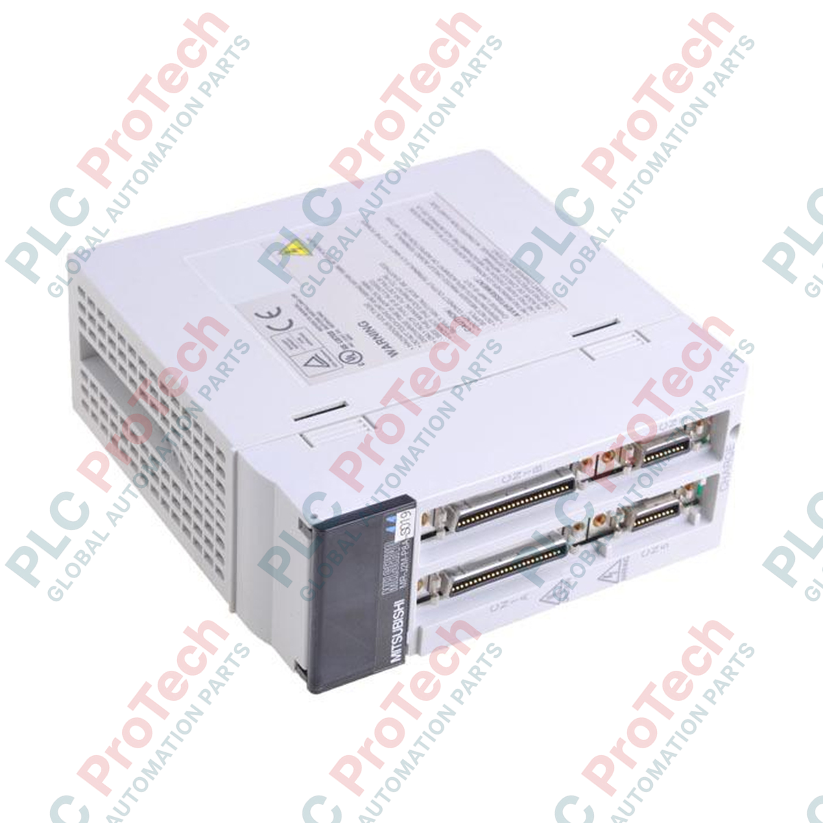
Centralized multi-axis motion architectures rely on high-density controller integration, and the Mitsubishi Electric MR-J2M-P8A-S019 serves as a dedicated general-purpose AC servo drive interface module for high-precision operations. Operating within the modular MELSERVO MR-J2M ecosystem, this unit consolidates control signals, fieldbus communication, and axis synchronization into a single chassis interface. Equipped with an 8-channel pulse train interface, it coordinates command signals for multiple modular drive slices while providing robust noise immunity. The integrated RS-232C and RS-422 interfaces simplify diagnostic coupling and multi-drop network configurations. Engineered with an IP00 open structure, this drive unit is designed for direct mounting inside standard industrial electrical enclosures to maximize space-efficiency and simplify high-density panel layouts.
Features
-
Multi-Axis Coordination: Manages up to 8 independent modular drive channels via synchronized pulse train logic.
-
Industrial Digital I/O Matrix: Integrates 40 signal inputs and 16 signal outputs for extensive PLC and peripheral handshaking.
-
Dual Serial Diagnostics: Dedicated 1-channel RS-232C for local PC diagnostics and 1-channel RS-422 for daisy-chained field operations.
-
Hardware-Level Safety: Dual-channel forced stop inputs and dual alarm outputs facilitate hardwired connection to safety relays.
-
Analog Monitoring: Features 3 analog monitor channels for real-time oscilloscope tracking of motor parameters and torque behavior.
Applications
- High-density packaging and sorting machines requiring synchronized multi-axis registration.
- Semiconductor manufacturing and pick-and-place gantry robots.
- Automated multi-station assembly lines and textile machinery.
- CNC tool changers and complex auxiliary indexing systems.
Technical Specifications
| Specification Parameter |
Value / Rating |
| Manufacturer |
Mitsubishi Electric |
| Model Number |
MR-J2M-P8A-S019 |
| Series |
MELSERVO MR-J2M Series |
| Product Type |
General-Purpose AC Servo Drive Control Unit |
| Control Power Supply |
Power supply circuit integrated for base unit (supporting up to 8 slots) |
| Pulse Train Interface |
8 channels (differential line driver or open-collector compatible) |
| Serial Communication Ports |
1x RS-232C port, 1x RS-422 port |
| Digital Inputs |
40 standard inputs, 2 forced stop input points |
| Digital Outputs |
16 standard outputs, 2 alarm output points |
| Analog Monitoring Channels |
3 channels (assignable tracking variables) |
| Enclosure Protection Class |
IP00 (Open Structure, requires protective cabinet housing) |
| Operating Temperature Range |
0 to 55 degC (non-freezing) |
| Shipping Weight (Calculated) |
2.00 kg |
Connections and Interfaces
| Port / Terminal Block |
Function / Circuit Assignment |
| Pulse Interface Block |
8 channels of pulse train input lines for individual axis command positioning. |
| RS-232C Port |
1x RJ45 or D-sub communication interface for direct connection to PC setup software. |
| RS-422 Port |
Multi-drop serial communication connector for centralized PLC networking. |
| Forced Stop Terminals |
2 points dedicated to emergency external cutoff signals for safety interlocks. |
| Analog Monitor Output |
3 pins for parameter signal output (speed, torque, and current feedback visualization). |
Alternative Models & Compatibility
The MR-J2M-P8A-S019 is a highly specialized variant in the MR-J2M multi-axis modular servo family. When replacing older MR-J2M standard control units, verify that the S019 suffix aligns with your host controller's specific digital I/O handshaking logic and bus timing. Ensure your MR Configurator software matches the firmware generation of this base unit to enable seamless parameter access across all 8 modular slots.
Application Pitfalls & Engineering Notes
Due to its IP00 open-frame structure, this unit offers zero protection against dust, condensation, or metallic particulates. It must always be integrated within a clean, forced-air-cooled IP54 enclosure. Furthermore, because it aggregates up to 8 axes of pulse commands, cable paths should be kept as short as possible to prevent signal degradation and cross-talk. Never run logic signals adjacent to the primary 3-phase AC power lines or motor output lines.
Commissioning & Wiring Tips
When wiring the high-density 40-point input and 16-point output blocks, utilize shielded multi-conductor cables and ground the shield at the cabinet entry point using a low-impedance grounding clamp. Ensure that the RS-422 multi-drop chain is terminated with a 150-ohm resistor at the last physical station in the loop to eliminate high-frequency signal reflections that can lead to intermittent communication dropouts.
Installation Guidelines
CRITICAL WARNING
Disconnect and isolate all primary power feeds before starting installation or maintenance work. Wait at least 20 minutes to allow the DC bus capacitors of connected amplifier modules to fully discharge. Always verify zero voltage at all terminals using a reliable digital multimeter before handling hardware components.
1
Mount the unit vertically onto a rigid, grounded metal backplate inside a sealed industrial enclosure, maintaining specified thermal clearances at the top and sides.
2
Establish a solid low-impedance ground connection from the unit's grounding terminal directly to the enclosure's main ground bus bar.
3
Connect the high-density I/O connectors, ensuring that the forced stop input signal circuit is fully closed and integrated with your machine's safety circuit.
4
Attach the RJ45 or D-sub communication lines, verifying that serial network addresses are properly configured on adjacent nodes before powering on the system.