Description
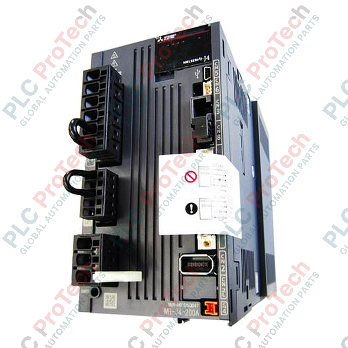
Providing high-speed, high-precision motion control within the MELSERVO-J4 architecture, the Mitsubishi Electric MR-J4-200B-RJ is a 2 kW rated output AC servo amplifier. This unit utilizes the fiber-optic SSCNET III/H network interface to deliver synchronous real-time control with minimal noise susceptibility. The -RJ suffix indicates its unique capability to support conversion units, enabling flexible integration with external encoder interfaces, CC-Link IE Field communication networks, or specialized absolute position detection systems. Operating on a three-phase input of 200 V AC to 240 V AC, this amplifier coordinates with HG-series rotary or linear servo motors to maintain exceptional loop response times in demanding industrial motion applications.
Key Features
-
High-Speed SSCNET III/H: Uses optical fiber communication to ensure noise-free, high-speed command transmission and precise multi-axis synchronization.
-
Specialized -RJ Compatibility: Supports interface conversion units to connect with alternative absolute feedback encoders and auxiliary networks.
-
Advanced Vibration Suppression: Built-in machine resonance filter and low-frequency vibration suppression algorithm to protect mechanical structures.
-
Robust Protective Functions: Integrated overcurrent shutoff, regenerative overvoltage shutoff, and motor overload (thermal overload) detection.
Applications
- Multi-axis CNC machining centers and high-speed milling systems.
- Precision semiconductor assembly, pick-and-place, and wafer handling systems.
- Automated packaging machinery, rotary indexing tables, and high-speed labeling systems.
- Cartesian and multi-joint industrial robotics requiring coordinated trajectory control.
Technical Specifications
| Parameter |
Specification Value |
| Manufacturer |
Mitsubishi Electric |
| Model Number |
MR-J4-200B-RJ |
| Series Name |
MELSERVO-J4 |
| Rated Output |
2.0 kW |
| Main Circuit Power Supply |
3-phase 200 V AC to 240 V AC, 50/60 Hz |
| Interface Type |
SSCNET III/H (with Conversion Unit Support) |
| Molded-Case Circuit Breaker (MCCB) |
30 A Frame (20 A Rated Current) |
| Magnetic Contactor |
DUD-N30 |
| Vibration Resistance |
5.9 m/s2, at 10 Hz to 55 Hz (X, Y, and Z axes) |
| Installation Environment |
Indoors (no direct sunlight), free of corrosive gas, oil mist, dust |
| Max Altitude |
2000 m or less above sea level |
| Net Mass |
2.1 kg |
| Shipping Weight |
3.0 kg |
Connections and Interfaces
| Connector / Terminal |
Functional Assignment |
| L1, L2, L3 |
Main circuit 3-phase AC input power terminal connections |
| U, V, W |
Servo motor power output phase terminals (must not be crossed) |
| CN1A / CN1B |
SSCNET III/H fiber-optic communication connection ports (IN / OUT) |
| CN2 |
Motor encoder feedback signal input connector |
| CN3 |
Analog monitor and auxiliary input/output port |
Empirical Engineering Insights
Alternative Models & Compatibility
The standard MR-J4-200B version is directly compatible with basic SSCNET III/H setups, but it lacks the interface translation layer of the -RJ variant. If you are substituting an older MR-J3-200B drive, you must run the system controller in J3 compatibility mode or migrate your network master parameters to SSCNET III/H. Note that the -RJ model allows the attachment of the MR-J4-T20 card for seamless transition to CC-Link IE Field networks without replacing the entire amplifier chassis.
Application Pitfalls & Engineering Notes
Ensure optimal space layout: because the unit dissipates up to 120 W under continuous maximum loads, adjacent amplifiers must maintain a minimum 10 mm clear lateral spacing unless derated. In highly reflective optical environments, or where optical fiber cables are tightly bent, AL.37 (Parameter Error) or AL.16 (Encoder Initial Communication Error) can trigger due to packet loss. Maintain a fiber-optic bend radius of at least 25 mm to prevent light transmission degradation.
Commissioning & Wiring Tips
Always connect the ground terminal (PE) of the servo motor directly to the ground terminal of the amplifier to suppress high-frequency EMI. Grounding the motor only to the machine frame can cause intermittent absolute encoder errors due to structural potential differences. When utilizing absolute position detection, ensure a compliant lithium-metal battery pack (such as the MR-BAT6V1SET) is installed and operational before attempting to clear home parameters.
Installation Guidelines
CRITICAL WARNING: Hazardous voltage levels up to 340 V DC may persist on the internal bus capacitors even after AC supply power is disconnected. Disconnect all primary power and wait at least 15 minutes before touching terminals. Confirm that the charge LED indicator on the front panel is completely extinguished before proceeding with wiring.
1
Mount the amplifier vertically on an unpainted metal electrical panel plate to optimize heat dissipation and ground path continuity.
2
Wire the main supply input (L1/L2/L3) through a designated 30 A Frame circuit breaker and magnetic contactor to protect internal diode bridges from line spikes.
3
Route motor output lines (U/V/W) separately from low-voltage signal wires (SSCNET fiber, encoder line, external I/O) to avoid capacitive cross-talk.
4
Connect the SSCNET III/H fiber-optic cables, verifying that they snap securely into CN1A and CN1B with their protective dust caps removed.