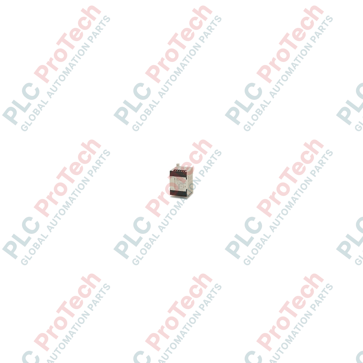
Description
Designed to provide compact and reliable control in localized industrial automation architectures, the Omron CPM1A-10CDT-A-V1 functions as a highly integrated micro-programmable logic controller. This unit combines memory, processing, and localized physical I/O within a single space-saving enclosure. Featuring 6 digital inputs and 4 transistor (sink) outputs, the controller is powered directly by an 85 to 264 VAC line supply, eliminating the need for external control power transformers in standard utility environments. Its integrated high-speed processing makes it optimal for localized machinery control, conveyor coordination, and dedicated subsystem execution.
Features
-
Integrated I/O Architecture: Features 10 onboard I/O points (6 inputs, 24 VDC; 4 transistor sink outputs) to handle basic sensing and actuation.
-
Universal AC Power Source: Operates reliably across a broad input range from 85 VAC to 264 VAC at 50/60 Hz.
-
Solid-State Outputs: Transistor (sink type) outputs allow high-frequency switching and reliable interfacing with electronic loads.
-
High-Speed Counters & Pulse Outputs: Equipped with 1 built-in encoder input (5 kHz) and 1 built-in pulse output (2 kHz) for entry-level positioning tasks.
-
Optimized Program Space: Includes 2 kWords of program memory capacity and 1 kWord of data memory.
Applications
-
Conveyor Control Systems: Manages localized sensor feedback, sorting gates, and speed indicators.
-
Packaging Equipment: Ideal for small form-fill-seal machines, labelers, and wrapper control loops.
-
HVAC Panel Integration: Controls pump sequencing, damper actuators, and fan operational cycles.
-
Specialized Machine Tools: Coordinates simple automated drills, pneumatic clamps, and feed mechanisms.
Technical Specifications
| Parameter |
Specification Value |
| Manufacturer |
Omron Industrial Automation |
| Model Number |
CPM1A-10CDT-A-V1 |
| Product Series |
CPM1A |
| Input Points |
6 Inputs (24 VDC) |
| Output Points |
4 Outputs (Transistor, Sink) |
| Power Supply Voltage |
85 to 264 VAC (50/60 Hz) |
| Program Memory Capacity |
2 kWords |
| Data Memory Capacity |
1 kWords |
| Logic Execution Speed |
0.72 us to 1.72 us (basic instructions) |
| High-Speed Inputs |
1 Encoder/Counter Input (5 kHz) |
| Pulse Outputs |
1 Pulse Output (2 kHz) |
| Expansion Support |
No (10-point micro blocks do not support I/O expansion) |
| Dimensions (H x W x D) |
90 mm x 66 mm x 70 mm |
| Shipping Weight (Calculated) |
0.45 kg |
Connections and Interfaces
| Terminal designation |
Functional Assignment |
| L1, L2/N |
AC Power Supply Inputs (85 to 264 VAC) |
| COM (Input) |
Common terminal for external 24 VDC input sensors |
| 00.00 to 00.05 |
DC Input Terminals (00.00 dedicated to High-Speed Counter/Encoder input) |
| OUT V- (COM) |
Negative common for transistor sink outputs |
| 10.00 to 10.03 |
Transistor Sink Output Terminals (10.00 dedicated to high-speed pulse output) |
Empirical Engineering Insights
Alternative Models & Compatibility
The CPM1A-10CDT-A-V1 replaces the non-V1 legacy CPM1A units directly. The V1 variant offers expanded internal command support and refined serial polling response characteristics. Note that because this is a 10-point module, it lacks the peripheral expansion bus connection found on the 20-point and larger CPU models; thus, I/O scaling requires replacement with a larger base CPU unit rather than adding expansion slices.
Application Pitfalls & Engineering Notes
When using the built-in transistor sink outputs (model designation "T"), pay strict attention to the cumulative current draw. Each output is rated for up to 0.3 A individually, but the total current passing through the common return bus must not exceed 0.9 A. Exceeding this thermal threshold will permanently damage the internal logic boards. If your application switches inductive DC solenoids, always install external flyback diodes across the loads to prevent destructive back-EMF spikes.
Commissioning & Wiring Tips
To utilize the high-speed 5 kHz encoder functionality on input terminal 00.00, use double-shielded twisted-pair cabling. Route this cable completely separate from the AC supply lines wired to terminals L1 and L2/N to avoid electrical noise coupling. Additionally, connect the frame ground terminal directly to a clean low-impedance earth ground to prevent internal memory register corruption caused by high-frequency electromagnetic interference.
Installation Guidelines
CRITICAL WARNING: Ensure all main AC power is fully de-energized at the isolation breaker prior to handling terminal connections. Allow at least 60 seconds after power down for internal capacitors to discharge completely before making adjustments to the wiring harness or connection ports.
1
Mount the controller onto a standard 35 mm DIN rail inside an enclosure rated at least IP54 to prevent atmospheric dust and condensation contamination.
2
Connect the primary AC line voltage (85 to 264 VAC) directly to the L1 and L2/N terminals using 1.25 mm square (16 AWG) copper wire.
3
Wire field input devices to terminals 00.00 through 00.05, and provide a stable external 24 VDC potential to the input common terminal.
4
Verify that the output wiring polarity matches standard sink configurations, ensuring the common output ground is correctly established prior to system startup.