Description
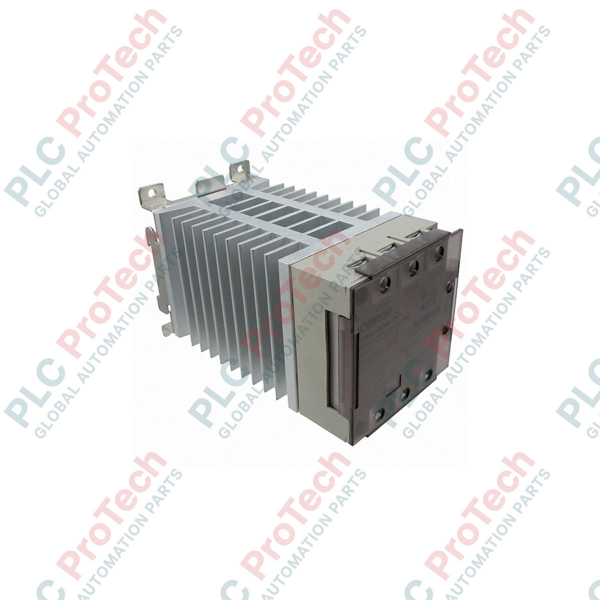
Providing precise, low-noise thermal regulation in demanding industrial environments, the Omron G3PE-245B-3N acts as a heavy-duty three-phase solid-state contactor engineered for high-frequency heater switching. Designed with a built-in heat sink and integrating advanced phototriac isolation, this device ensures safe galvanic separation between the control logic and high-power load circuits. The integrated zero-cross function suppresses electromagnetic interference by synchronizing load activation with the AC voltage zero points, making it highly compatible with noise-sensitive automation environments.
Features
-
Three-Phase Control: Equipped with 3 switched poles (3-element configuration) for comprehensive load isolation.
-
Zero-Cross Switching: Minimizes electrical noise and surge currents during initial power-up states.
-
Robust Isolation: High-performance phototriac coupler protects PLC/controller outputs from load-side transients.
-
Physical Durability: Solid-state construction eliminates mechanical wear, dramatically extending operational lifetimes compared to traditional electromagnetic contactors.
-
Convenient Terminal Layout: Heavy-duty screw terminals support secure ring and fork crimp connections.
Applications
- Plastic injection molding and extrusion barrel heating
- Industrial reflow ovens and industrial drying systems
- Semiconductor manufacturing thermal chamber controllers
- Packaging machinery shrink tunnels and sealing bars
Technical Specifications
| Manufacturer |
Omron |
| Model Number |
G3PE-245B-3N |
| Device Type |
3-Phase Solid State Relay (Heater Control) |
| Number of Elements |
3-phase, 3-element |
| Rated Control Voltage |
12 to 24 VDC |
| Operating Voltage Range |
9.6 to 30 VDC |
| Input Current |
10 mA max. (at 24 VDC) |
| Must Operate Voltage |
9.6 VDC max. |
| Must Release Voltage |
1 VDC min. |
| Rated Load Voltage |
100 to 240 VAC (50/60 Hz) |
| Load Voltage Range |
75 to 264 VAC (50/60 Hz) |
| Load Current |
45 A (at 40 degC) |
| Minimum Load Current |
0.5 A |
| Inrush Current Resistivity |
440 A (60 Hz, 1 cycle) |
| Permissible I2t |
1260 A2s |
| Applicable Load Capacity |
15.5 kW (at 200 VAC) |
| Isolation Method |
Phototriac |
| Zero Cross Function |
Equipped |
| Terminal Structure |
Screw terminal |
| Shipping Weight (Calculated) |
3.0 kg |
Connections and Interfaces
| Terminal Designation |
Terminal Class |
Description / Function |
| A1 (+) / A2 (-) |
Input Terminal |
DC Control Voltage Input (12 to 24 VDC trigger signal) |
| L1 / L2 / L3 |
Load Line Input |
3-Phase AC power line input connections (100 to 240 VAC) |
| T1 / T2 / T3 |
Load Output |
3-Phase AC power connection directly to the heating elements |
Empirical Engineering Insights
Alternative Models & Compatibility
The "3N" suffix denotes a 3-phase, 3-element controller which switches all three distinct phases. If replacing older 2-element models (such as the G3PE-245B-3, which only switches two phases while passing the third directly), verify panel wiring diagrams. The 3-element version provides superior isolation and meets stricter safety codes requiring all phase lines to be interrupted during off-cycles.
Application Pitfalls & Engineering Notes
Solid state relays generate approximately 1.5 Watts of heat per Ampere of load current. When installing this 45 A unit in fully enclosed control panels, calculate total thermal load and ensure adequate air circulation or force-cooling. Ambient temperature inside the panel must not exceed 40 degC to maintain the full 45 A rating without derating the device.
Commissioning & Wiring Tips
To prevent localized overheating and terminal failure under high current loads, use crimp-style closed-loop ring terminals for the main load lines (L1/L2/L3 and T1/T2/T3). Ensure all load terminals are tightened to a torque rating between 1.47 and 2.45 N-m. Periodically inspect connection torque during routine plant maintenance cycles.
Installation Guidelines
CRITICAL WARNING: Hazardous voltages are present on the main circuit terminals. Disconnect and lock out all upstream primary power supplies before executing installation, maintenance, or wiring procedures on this equipment. Verify residual voltage on all terminals using an appropriately rated digital multimeter.
1
Mount the unit vertically on a standard 35mm DIN rail or directly to a metallic back panel using the integrated mounting screw holes. Ensure the integrated heat sink fins are oriented vertically to facilitate optimal natural convective airflow.
2
Wire the 12 to 24 VDC control input line from your PLC, temperature controller, or safety logic solver to the A1 (+) and A2 (-) terminals.
3
Connect the incoming 3-phase power line utility supply wires to the input terminals labeled L1, L2, and L3 using high-temperature rated industrial wire.
4
Route the load output terminals T1, T2, and T3 to the heating element terminals. Double-check that all phase paths are configured correctly relative to delta or star heater wiring configurations.