Description
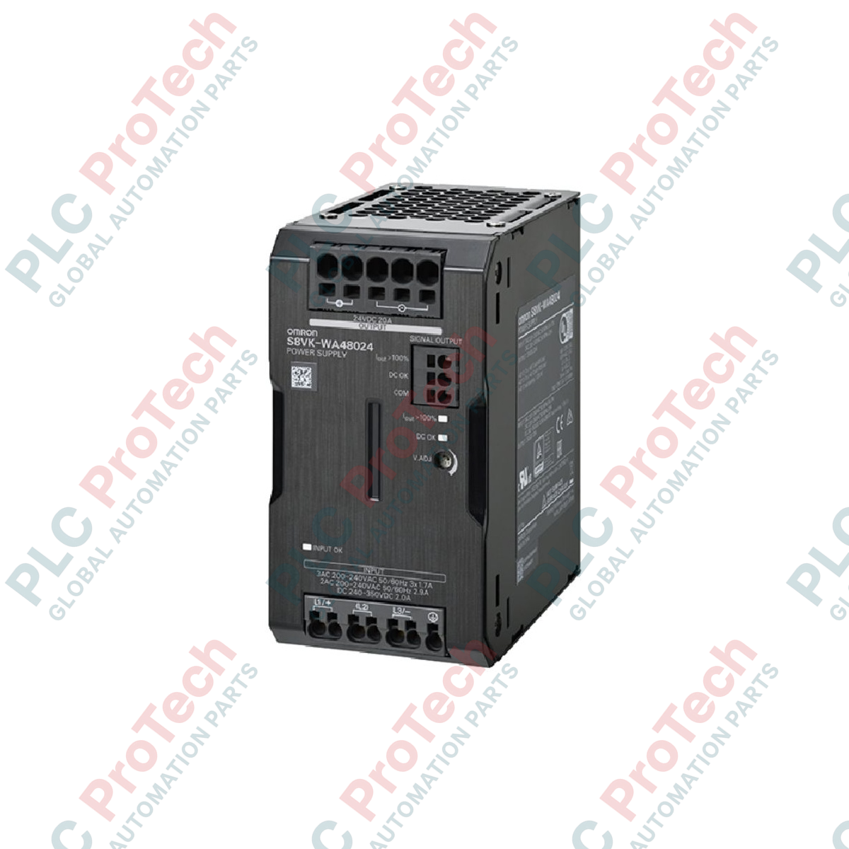
Delivering high-efficiency electrical conversion in demanding industrial environments, the Omron S8VK-WA48024 is a switch-mode power supply designed for three-phase electrical infrastructures. This 480 W unit converts a nominal three-phase 200 to 240 VAC input down to a stable 24 VDC output, maintaining tight voltage regulation even under fluctuating line conditions. Built with Push-In Plus terminal blocks, it significantly reduces panel wiring time while ensuring robust resistance to physical vibration. Its compact footprint and high-density design allow side-by-side mounting to optimize space inside control cabinets.
Features
-
Stable Three-Phase Operation: Designed specifically for three-phase 200 to 240 VAC inputs, preventing phase-imbalance issues in large automated systems.
-
Dynamic Boost Current: Delivers up to 30 A of peak boost current to handle high-inrush startup loads from capacitive components, solenoid valves, and DC motors.
-
Push-In Plus Technology: Front-facing connection terminals designed for rapid, toolless wiring that minimizes terminal loosening over time.
-
Rugged Environmental Design: IP20 protection housing engineered to withstand harsh industrial environments.
-
DIN Rail Mounting: Built-in robust slide-lock mechanism for direct snap-on mounting to standard symmetrical 35mm DIN rails.
Applications
-
Automotive Assembly Lines: Distributing stable 24 VDC control power to PLCs, industrial networks, and human-machine interfaces (HMIs).
-
Semiconductor Processing Equipment: Powering precision sensors, actuators, and electronic control relays.
-
Packaging and Material Handling: Supplying startup boost current for dynamic conveyor motors and pneumatic controllers.
-
Main Distribution Panels: Serving as the primary low-voltage DC bus feed within high-voltage sub-panels.
Technical Specifications
| Parameter |
Specification Value |
| Manufacturer |
Omron |
| Model Code |
S8VK-WA48024 |
| Series Name |
S8VK-W |
| Input Voltage Range |
Three-phase, 200 to 240 VAC (Allowed: 170 to 264 VAC) |
| Output Voltage |
24 VDC |
| Rated Power Output |
480 W |
| Rated Output Current |
20 A |
| Maximum Boost Current |
30 A |
| Connection Method |
Push-In Plus Terminal Blocks |
| Enclosure Class |
IP20 (EN/IEC 60529) |
| Operating Temperature Range |
-40 to +70 degC (With derating above 40 degC) |
| Physical Unit Weight |
1.05 kg |
| Shipping Weight |
2.50 kg |
Connections and Interfaces
| Terminal Group |
Designation |
Function Assignment |
| Input Section (Top) |
L1 |
AC Input Phase 1 |
| L2 |
AC Input Phase 2 |
| L3 |
AC Input Phase 3 |
| PE |
Protective Earth Ground Connection |
| Output Section (Bottom) |
+V (x2) |
Positive 24 VDC Output Terminals |
| -V (x2) |
Negative DC Return Terminals |
Empirical Engineering Insights
Alternative Models & Compatibility
When replacing older, single-phase power setups (such as the S8VK-G series) with the S8VK-WA48024, ensure that the mechanical panel space matches, as three-phase models have a slightly different width. The S8VK-W family is directly backwards compatible with standard DIN rail accessories but requires three-phase feed protection branch circuit breakers configured for motor-rated curves to avoid nuisance trips on initial charge.
Application Pitfalls & Engineering Notes
While the S8VK-WA48024 is robust, running it continuously with unbalanced input phases will degrade internal capacitors. A common field mistake is installing the power supply inside a completely sealed, non-ventilated box with other high-heat components. Maintain a minimum 10mm lateral gap between adjacent devices to allow natural convection, preventing thermal derating from restricting output capacity below the rated 20 A.
Commissioning & Wiring Tips
Always use insulated pin terminals (ferrules) with the Push-In Plus system to ensure absolute contact integrity. For solid or ferruled wires, push directly into the insertion hole. When using stranded wire without ferrules, insert a flat screwdriver into the orange release button hole first to open the internal clamp mechanism before guiding the wire inside.
Installation Guidelines
CRITICAL WARNING: RISK OF ELECTRICAL SHOCK, EXPLOSION, OR ARC FLASH. Turn off all input power supplying this device before installation, wiring, or maintenance. Confirm that the three-phase power supply lines (L1/L2/L3) are completely de-energized. Allow internal storage capacitors to discharge for at least 5 minutes after removing power before touching any terminal connections.
1
Hook the top side of the power supply's integrated DIN bracket onto the top edge of the 35mm DIN rail.
2
Press the lower portion of the housing firmly downward and backward until the spring lock snaps into place onto the bottom edge of the rail.
3
Connect the PE (Protective Earth) ground terminal to a low-impedance system ground point before connecting the AC phase lines.
4
Insert pre-insulated ferrules for L1, L2, and L3 into the corresponding input terminals, and +V/-V into the output terminals. Verify that there are no exposed loose copper strands.