Description
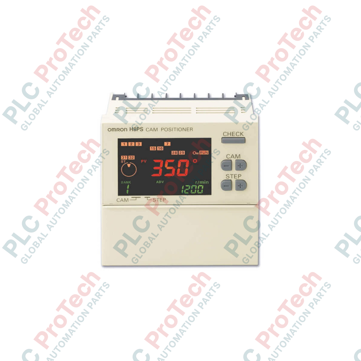
For high-precision rotary angle detection and coordinated output control in automated packaging, assembly, and stamping systems, the Omron H8PS-32B provides an exceptional, solid-state electronic replacement for mechanical cam systems. This panel-mounted controller processes signals from an absolute rotary encoder to drive up to 32 NPN transistor outputs based on pre-programmed angular windows. Featuring a compact 1/4 DIN form factor (96 x 96 mm) and an integrated backlit LCD screen, the device allows for rapid angle monitoring, direct programming, and manual parameter adjustment without requiring external configuration software.
Key Features
-
High-Density Output: 32 dedicated NPN transistor outputs for complex multi-cam control sequences.
-
DIP Switch Direction Selection: Simplifies setup by allowing mechanical forward (CW) or reverse (CCW) rotation direction switching directly on the unit.
-
1/4 DIN Enclosure: Standard 96 x 96 mm panel-mount housing saves control cabinet space and simplifies retrofitting.
-
Backlit LCD Interface: High-visibility display ensures clear operation diagnostics and monitoring even in dimly lit industrial environments.
-
Absolute Encoder Compatibility: Accepts direct inputs from absolute rotary encoders for robust position retention through power cycles.
Typical Industrial Applications
- High-speed rotary packaging and wrapping machinery synchronization.
- Metal forming and stamping press timing control.
- Gluing, sealing, and labeling machine dispenser triggers.
- Intermittent motion conveyor positioning and sorting operations.
Technical Specifications Table
| Specification Parameter |
Technical Value |
| Manufacturer |
Omron |
| Model Part Number |
H8PS-32B |
| Product Type |
Solid-State Cam Positioner |
| Number of Outputs |
32 Outputs |
| Output Type |
NPN Transistor |
| Input Type |
Absolute Rotary Encoder |
| Supply Voltage Range |
24 VDC (Operating range: 20.4 to 26.4 VDC) |
| Dimensions |
96 x 96 x 84.5 mm (1/4 DIN standard) |
| Display |
LCD with Backlight |
| Rotation Switching |
DIP switch selectable (CW / CCW) |
| Mounting Type |
Panel Mount |
| Net Weight |
Approx. 300 g |
| Shipping Weight (Calculated) |
1.5 kg |
| Package Dimensions (Calculated) |
150 x 150 x 150 mm |
Empirical Engineering Insights
Alternative Models & Compatibility
The H8PS-32B is the high-density NPN variant in the H8PS family. If PNP switching logic is required by your PLC or digital input cards, the PNP-equivalent models (such as the H8PS-32BP) must be selected instead, as output polarity is fixed. This controller is designed for optimal plug-and-play operation with standard Omron E6C3-A absolute rotary encoders.
Application Pitfalls & Engineering Notes
When using high-speed absolute encoders, electromagnetic noise generated by nearby variable frequency drives (VFDs) can corrupt the gray-code positioning data. It is critical to route the encoder signals through dedicated, shielded twisted-pair cabling separated from power-carrying conductors to prevent positioning errors or tracking offsets.
Commissioning & Wiring Tips
Always set the rotation direction DIP switch (CW vs. CCW) prior to powering up the unit. The H8PS-32B reads configuration switch positions only during its initialization phase. Changing these settings during active runtime will not dynamically update the operational logic and may result in an output tracking mismatch.
Installation Guidelines
CRITICAL WARNING: De-energize all primary, secondary, and auxiliary power circuits before attempting to mount, wire, or adjust the H8PS-32B cam positioner. Failure to isolate power can result in electrical shock, equipment destruction, or accidental machine actuation.
1
Prepare a standard 1/4 DIN (92 x 92 mm +0.8/-0 mm) square panel cutout and insert the unit from the front, securing it with the provided mounting brackets.
2
Configure the mechanical rotation direction (CW/CCW) and pulse parameters via the physical DIP switches on the unit frame before applying control voltage.
3
Connect the absolute encoder cable to the dedicated front-facing or rear interface, ensuring the shield is securely tied to functional ground at the panel entry point.
4
Wire the 24 VDC supply voltage and the NPN transistor output lines to their respective terminal block channels, verifying polarity and load constraints before testing.